Designing a Power Supply with Multiple Input Options
advertisement

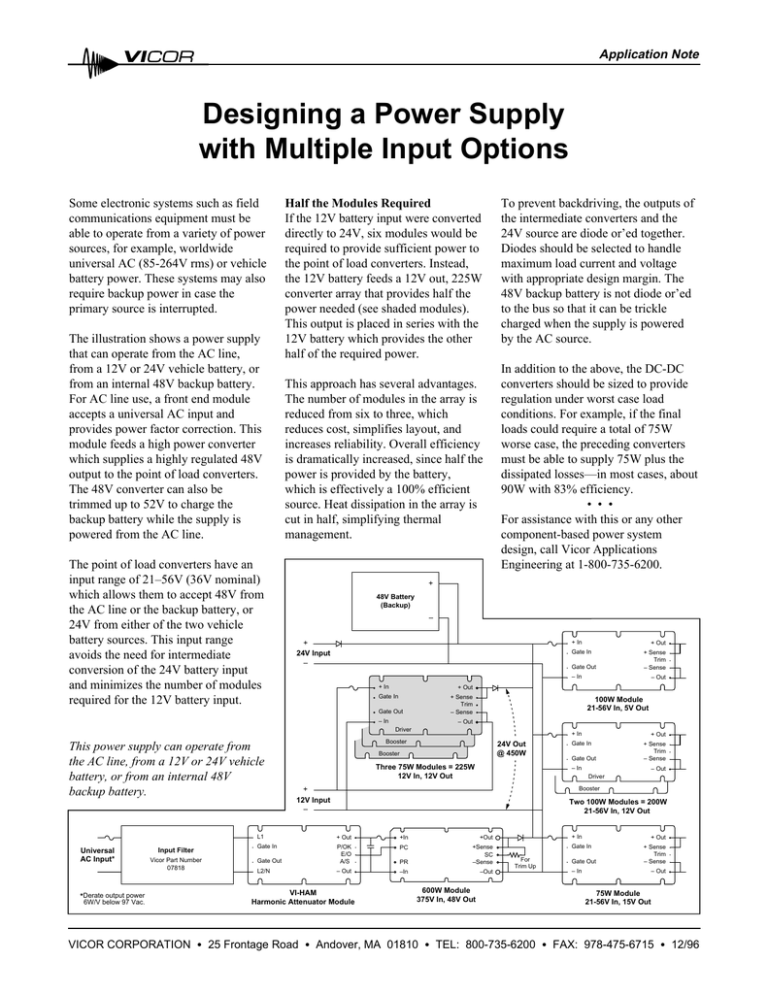
Application Note Designing a Power Supply with Multiple Input Options Some electronic systems such as field communications equipment must be able to operate from a variety of power sources, for example, worldwide universal AC (85-264V rms) or vehicle battery power. These systems may also require backup power in case the primary source is interrupted. The illustration shows a power supply that can operate from the AC line, from a 12V or 24V vehicle battery, or from an internal 48V backup battery. For AC line use, a front end module accepts a universal AC input and provides power factor correction. This module feeds a high power converter which supplies a highly regulated 48V output to the point of load converters. The 48V converter can also be trimmed up to 52V to charge the backup battery while the supply is powered from the AC line. The point of load converters have an input range of 21–56V (36V nominal) which allows them to accept 48V from the AC line or the backup battery, or 24V from either of the two vehicle battery sources. This input range avoids the need for intermediate conversion of the 24V battery input and minimizes the number of modules required for the 12V battery input. Half the Modules Required If the 12V battery input were converted directly to 24V, six modules would be required to provide sufficient power to the point of load converters. Instead, the 12V battery feeds a 12V out, 225W converter array that provides half the power needed (see shaded modules). This output is placed in series with the 12V battery which provides the other half of the required power. This approach has several advantages. The number of modules in the array is reduced from six to three, which reduces cost, simplifies layout, and increases reliability. Overall efficiency is dramatically increased, since half the power is provided by the battery, which is effectively a 100% efficient source. Heat dissipation in the array is cut in half, simplifying thermal management. To prevent backdriving, the outputs of the intermediate converters and the 24V source are diode or’ed together. Diodes should be selected to handle maximum load current and voltage with appropriate design margin. The 48V backup battery is not diode or’ed to the bus so that it can be trickle charged when the supply is powered by the AC source. In addition to the above, the DC-DC converters should be sized to provide regulation under worst case load conditions. For example, if the final loads could require a total of 75W worse case, the preceding converters must be able to supply 75W plus the dissipated losses—in most cases, about 90W with 83% efficiency. • • • For assistance with this or any other component-based power system design, call Vicor Applications Engineering at 1-800-735-6200. + 48V Battery (Backup) – + 24V Input – + In Gate Out Gate In + Sense Trim – Sense 100W Module 21-56V In, 5V Out – Out Driver Input Filter Vicor Part Number 07818 *Derate output power 6W/V below 97 Vac. VICOR CORPORATION – Out + Out – In Universal AC Input* + Sense Trim – Sense – In + In Gate Out This power supply can operate from the AC line, from a 12V or 24V vehicle battery, or from an internal 48V backup battery. + Out Gate In + In Booster 24V Out @ 450W Booster Three 75W Modules = 225W 12V In, 12V Out + Out Gate In Gate Out + Sense Trim – Sense – In – Out Driver Booster + 12V Input – Two 100W Modules = 200W 21-56V In, 12V Out L1 + Out +In +Out Gate In PC Gate Out P/OK E/O A/S PR +Sense SC –Sense L2/N – Out –In –Out VI-HAM Harmonic Attenuator Module 600W Module 375V In, 48V Out + In + Out Gate In For Trim Up Gate Out + Sense Trim – Sense – In – Out 75W Module 21-56V In, 15V Out • 25 Frontage Road • Andover, MA 01810 • TEL: 800-735-6200 • FAX: 978-475-6715 • 12/96

