1 OF 6
Installation Instructions
MX LED Enhanced Color Adjustable
! WARNING
Risk of electrical shock. Disconnect power
before servicing or installing luminaire.
! WARNING
Risk of injury or damage. Luminaire will
fail if not installed properly. Follow
installation instructions.
! WARNING
Risk of injury. Wear safety glasses and
gloves during installation and servicing.
Allow ample time to cool before handling.
IS-R1048R2
IMPORTANT SAFETY INSTRUCTIONS
–– Read all installation instructions before installing. It is important to save these instructions.
–– Only install and connect LED module with power disconnected at the circuit breaker. Hot plugging, or connecting the module with
power on, could damage the LEDs and is not covered by warranty.
–– Connectors on modules and approved housings are keyed for specific voltage combinations; do not force or attempt to bypass
connectors.
–– Observe and follow all label information and instructions regarding dry, damp and wet location listings, proper Intense LED module,
warnings of installation near combustible materials and/or insulation.
–– Turn off power at circuit breaker before attempting to install or perform maintenance on the fixtures.
–– Be sure to connect ground wire to prevent electric shock or other potential hazards.
–– The product must be installed in a manner consistent with the intended use and in compliance with the national electrical codes and
local codes by a person familiar with the construction and operation of the product and the hazards involved.
–– Do not block the trim aperture as this may cause unsafe operating conditions.
–– WARNING: RISK OF FIRE. Non-IC fixture requires that insulation must be kept at least 3” away from all sides of the fixture.
Minimum of 90°C supply conductors. Consult a qualified electrician before installation.
WARNING: Use only Intense Lighting trims listed for use with this fixture. Use of trims other than those listed by Intense Lighting is a
violation of N.E.C 110-3(B) and voids all warranties.
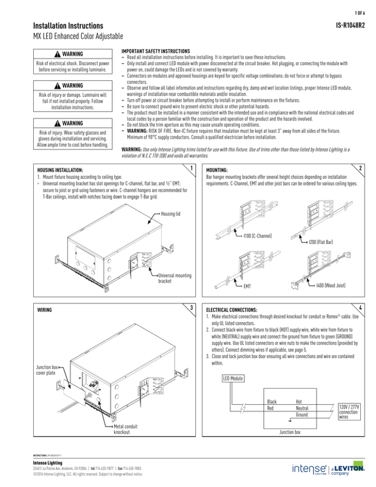
1
HOUSING INSTALLATION:
1. Mount fixture housing according to ceiling type.
-- Universal mounting bracket has slot openings for C-channel, flat bar, and 1/2” EMT;
secure to joist or grid using fasteners or wire. C-channel hangers are recommended for
T-Bar ceilings, install with notches facing down to engage T-Bar grid.
2
MOUNTING:
Bar hanger mounting brackets offer several height choices depending on installation
requirements. C-Channel, EMT and other joist bars can be ordered for various ceiling types.
Housing lid
I100 (C-Channel)
Universal mounting
bracket
3
WIRING
Junction box
cover plate
I200 (Flat Bar)
I400 (Wood Joist)
EMT
4
ELECTRICAL CONNECTIONS:
1. Make electrical connections through desired knockout for conduit or Romex® cable. Use
only UL listed connectors.
2. Connect black wire from fixture to black (HOT) supply wire, white wire from fixture to
white (NEUTRAL) supply wire and connect the ground from fixture to green (GROUND)
supply wire. Use UL listed connectors or wire nuts to make the connections (provided by
others). Connect dimming wires if applicable, see page 5.
3. Close and lock junction box door ensuring all wire connections and wire are contained
within.
LED Module
Black
Red
Metal conduit
knockout
INSTRUCTIONS L/M-08032016 P-1
Intense Lighting
3340 E La Palma Ave, Anaheim, CA 92806 | tel 714 630-9877 | fax 714 630-9883
©2016 Intense Lighting, LLC. All rights reserved. Subject to change without notice.
Hot
Neutral
Ground
Junction box
120V / 277V
connection
wires
2 OF 5
IS-R1048R2
HOUSING HEIGHT ADJUSTMENT:
Loosen wingnut to make adjustments so that housing collar is flush with ceiling line.
5
TRIMLESS INSTALLATION:
1. Screw perforated mud plate to housing with #8 drywall screws (by others).
2. Reinstall plenum cover to prevent paint damage to fixtures.
3. Apply joint compound over perforated mud plate and feather out accordingly.
6
Wingnut
Ceiling line
Plenum cover
Housing
collar
Mud plate
Screws
7
TRIMLESS INSTALLATION (B):
1. Screw in mud plate into drywall.
Note: Do not remove plenum cover until mud and
paint has been applied
MODULE INSTALLATION:
1. Ensure bracket is at a 0° angle.
2. Check that power is off at breaker, hot plugging may damage LEDs.
3. Connect female quick connect from housing to male quick connect on module.
4. Snap module into channel and confirm module sits parallel to ceiling line and is
securely fastened into housing.
8
Quick connect
Channel
Screw in mud plate into drywall
9
ADJUSTING HORIZONTAL ADJUSTMENT:
1. Loosen thumb screw to allow fixture to adjust horizontally.
2. Place philips screw driver into adjustment assist to rotate module to desired horizontal
position.
3. Tighten thumb screw to lock horizontal rotation.
Thumb screw
(Horizontal locking)
10
ADJUSTING VERTICAL ADJUSTMENT:
1. Loosen knurled head thumb screw to allow fixture to adjust vertically.
2. Place philips screw driver into adjustment assist to rotate module to desired vertical
position.
3. Tighten knurled head thumb screw to lock vertical rotation, by hand or with 2.5mm hex
key.
Thumb screw
(Vertical locking)
Adjustment assist
(Hot aiming)
INSTRUCTIONS L/M-08032016 P-2
Intense Lighting
3340 E La Palma Ave, Anaheim, CA 92806 | tel 714 630-9877 | fax 714 630-9883
©2016 Intense Lighting, LLC. All rights reserved. Subject to change without notice.
Adjustment assist
(Hot aiming)
3 OF 6
IS-R1048R2
TRIM INSTALLATION (APPLIES TO ROUND HOUSING ONLY):
1. Position trim label to trim location label on the housing collar.
2. Snap trim into the housing.
3. Trim must line up parallel with the module when it is at the 35° position (as shown).
11
Trim label
Trim label
Trim parallel at
35° position
TRIM INSTALLATION (APPLIES TO SQUARE HOUSING ONLY):
1. Position trim label to trim location label on the housing collar.
2. To install trim, rotation plate must be parallel with the housing. Note: Trim will not lineup at any other angle than 90º increments.
Rotation
plate
Trim label
Trim label
OPTIC REPLACEMENT:
1. Remove trim, then remove module from channel and disconnect quick connect.
2. Rotate release cap by turning counter clockwise.
3. Set cap and retainer ring aside and change optics.
4. Align optic pins to holes on the module.
Module
Optic
Optic holes
Optic Holder
Retainer ring
Release cap
INSTRUCTIONS L/M-08032016 P-3
Intense Lighting
3340 E La Palma Ave, Anaheim, CA 92806 | tel 714 630-9877 | fax 714 630-9883
©2016 Intense Lighting, LLC. All rights reserved. Subject to change without notice.
Housing
4 OF 6
IS-R1048R2
DRIVER REPLACEMENT:
1. Adjust vertical angle to 0° and remove module from channel and disconnect quick connect.
2. Unscrew all four 2mm allen key head machine screws on both sides.
3. Remove vertical adjustment assembly by tilting the assembly to assure clearance.
4. Unsnap driver plate from junction box. Disconnect quick connect from the driver to interface.
5. Guide driver/driver plate through opening.
6. Replace new driver on driver plate and reconnect interface quick connect.
Module quick
connect
Allen head machine
screws
INSTRUCTIONS L/M-08032016 P-4
Intense Lighting
3340 E La Palma Ave, Anaheim, CA 92806 | tel 714 630-9877 | fax 714 630-9883
©2016 Intense Lighting, LLC. All rights reserved. Subject to change without notice.
Vertical
adjustment
assembly
Input quick
connect
Driver plate
Ceiling
opening
Interface
quick connect
5 OF 6
0-10V Dimming and Tuning Control Functions
Tunable White only
Wiring Diagram
Compatible Control Systems
Dimmer By Others
CCT
Dimming
For 0-10V Continuous CCT Control. Connect a 0-10V
control device to the blue (+) and white
(ground) wires. When the fixture is powered up, the
0-10V control will adjust the CCT over the tunable
range.
Tunable White & Dynamic Dimming
A 0-10V control may also be added for dimming
(as shown). Adjustments to Dimming levels are a
percentage of the 0-10V Dim setting (Trim). If a 0-10V
control is not used for dimming, the gray (ground) and
violet (+) wires must be grounded together.
Blue (TW only)
White (TW only)
LED
Grey
Luminaire
Violet
LED
Luminaire
Hot (Black)
Neutral (White)
Ground (Green)
Brand
Model
LevitonIP710-DLX
LevitonIP710-LFZ
LevitonSapphire
LevitonOmnitouch
Lutron
Diva, DVTV
Lutron
Nova-T, NTFTV
Lutron
Diva, NFTV
Lutron
Grafik Eye -GRX-TVI with GRX3503
Lutron
Energi Savr Node - QSN-4T16-S
Lutron
TVM2 Module
LightolierV2000FAMU
LightolierZP600FAM120
LightolierMP1500FAM120
Watt Stopper
DCLV1
TW = Tunable White - Example: MXDRTRTW1
DMX RDM Dimming and Tuning Control Functions
Standard default is Ch 1 dimming and Ch 2 CCT Control for Tunable White.
Standard default is Ch 1 for Dynamic Warm Dimming
DMX Control Options
1. Warm dim mode: In this mode, the luminaire warms
as it dims. It uses only one DMX-channel.
2. CCT tuning mode: In this mode, luminaire’s CCT
tunes along the black body curve. It uses two
DMX-channels, one for Brightness control and one
for CCT tuning
Compatible Control Systems
Wiring Diagram
LED
Luminaire
LED
Luminaire
Hot (Black)
Neutral (White)
Ground (Green)
Brand
Model
AcuityFresco
DMXister
DMXister test suite
NXP
NXP RDM SDK
Pathway Connect
Pathport
Open Lighting Project
RDM test suite
Ground (Brown/White)
Data DMX + (Orange/White)
Data DMX - (Orange)
DALI Dimming and Tuning Control Functions
DALI Control Functions
The luminaire can be operating in two different modes:
- Dynamic warm dimming mode, DALI device type 6
(DT6) compatible (Control gear 102)
- CCT tuning mode, DALI device type 8 (DT8) compatible
(Control gear: 209 Color control)
By default the unit will start up in warm dimming
mode with base address 0, but when it receives a DT8
command (dim warm/cool) it will switch to the CCT
tuning mode. It cannot switch automatically back.
Only a special DALI command (SetTcPHY_coolest=0) or
resetting the ARD function will set it back to the warm
dimming mode. This should not be done dynamically
as there are only a limited amount of resets possible
(10,000).
Wiring Diagram
Compatible Control Systems
LED
Luminaire
Hot (Black)
Neutral (White)
Ground (Green)
DALI DA (Orange)
DALI DA (Orange/White)
INSTRUCTIONS L/M-08032016 P-5
Intense Lighting
3340 E La Palma Ave, Anaheim, CA 92806 | tel 714 630-9877 | fax 714 630-9883
©2016 Intense Lighting, LLC. All rights reserved. Subject to change without notice.
LED
Luminaire
Brand
Leviton
Hadler
Lunatone
Model
DALI Controller CD250-C
DALI uP
DALI Switch 86459793
6 OF 6
INTENSE LIGHTING WARRANTY
INTERIOR LED PRODUCTS: 5-YEAR LIMITED WARRANTY
Intense Lighting warrants the LED electronics and components of its properly installed EXTERIOR LED products listed
below, to be free of defects in material and workmanship in normal use, for a period of five years from the date of our
shipment and warrants the painted finish for a period of one year from the date of our shipment.
Intense Lighting will repair or replace, at its option, any warranted product returned to it that it determines to be
defective. This limited warranty does not include installation or removal. In addition to complete failure, defects include
lumen depreciation to levels below 70% of initial lumen output within warranty period and/or color shift beyond that
which is set forth in the Energy Star Program Requirements for SSL – Version 1.1 within warranty period. The painted
finish of the product will be considered defective in material or worksmanship only if there is substantial deterioration in
the form of blistering, cracking, or peeling.
Defects do not include improper installation or operation, alterations, power surges or overheating due to external
conditions. The painted finish is not warranted against fading or chalking, as it may naturally flake or chalk over time
due to normal aging. To receive credit for defective merchandise, product must undergo quality inspection prior to the
processing of credit. If the product is found defective, you will be issued a credit. Product in good working condition will
not receive a credit. Please inform your accounting department to not short pay or issue any debits to our company
regarding a return. Testing and evaluation can take approximately 1-2 weeks based on quantity. At that time you will be
notified if credit is granted for your warranty return.
THE ABOVE EXPRESS WARRANTY STATES THE FULL AND COMPLETE OBLIGATION OF INTENSE LIGHTING. ALL IMPLIED
WARRANTIES OF MERCHANTABILITY OR FITNESS FOR A PARTICULAR PURPOSE ARE LIMITED IN DURATION TO THE
TERM OF THE EXPRESS WARRANTY. UNDER NO CIRCUMSTANCES WILL INTENSE LIGHTING ACCEPT LIABILITY FOR ANY
CONSEQUENTIAL SPECIAL OR INDIRECT DAMAGES WHETHER ARISING OUT OF CONTRACT, TORT, OR STRICT LIABILITY.
INSTRUCTIONS L/M-08032016 P-6
Intense Lighting
3340 E La Palma Ave, Anaheim, CA 92806 | tel 714 630-9877 | fax 714 630-9883
©2016 Intense Lighting, LLC. All rights reserved. Subject to change without notice.

