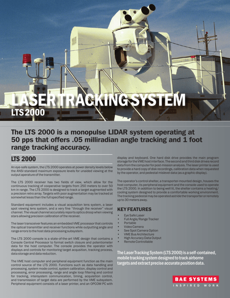
LASER TRACKING SYSTEM
LTS 2000
The LTS 2000 is a monopulse LIDAR system operating at
50 pps that offers .05 milliradian angle tracking and 1 foot
range tracking accuracy.
LTS 2000
An eye-safe system, the LTS 2000 operates at power density levels below
the ANSI standard maximum exposure levels for unaided viewing at the
output aperature of the transmitter.
display and keyboard. One hard disk drive provides the main program
storage for the VME host interface. The second and third disk drives record
data from the computer for post-mission analysis. The laser printer is used
to provide a hard copy of disk recordings, calibration data when requested
by the operator, and pedestal mislevel data (as a graphic display).
The LTS 2000 receiver has two fields of view, which allow for the
continuous tracking of cooperative targets from 250 meters to over 50
km in range. The LTS 2000 is designed to track a target augmented with
a precision retro array. Targets with poor augmentation may be tracked at
somewhat lesss than the full specified range.
The operator’s control shelter, a transporter-mounted design, houses the
host computer, its peripheral equipment and the console used to operate
the LTS 2000. In addition to being well lit, the shelter contains a heating/
cooling system designed to provide a comfortable working environment.
The tracking pedestal may be operated astride the transporter or remotely
up to 30 meters away.
Standard equipment includes a visual acquisition lens system, a laser
spot viewing lens system, and a very fine “through the receiver” visual
channel. The visual channel accurately reports optics droop when viewing
stars allowing precision calibration of the receiver.
KEY FEATURES
The laser transceiver features an embedded VME processor that controls
the optical transmitter and receiver functions while outputting angle and
range errors to the host data processing subsystem.
The LTS 2000 console is a state-of-the-art VME design that contains a
Console Central Processor to format switch closure and potentiometer
data for the host computer. The console provides the operator with
displays and controls for monitoring target acqusition, tracking process,
data storage and data reduction.
The VME host computer and peripheral equipment function as the main
control source of the LTS 2000. Functions such as data handling and
processing, system mode control, system calibration, display control and
processing, error processing, range and angle loop filtering and control
for tracking, intersystem communication, timing, acquisition control,
and transmission of target data are performed by the VME subsystem.
Peripheral equipment consists of a laser printer, and an OPCOM PC with
•
•
•
•
•
•
•
•
Eye Safe Laser
Full Angle/Range Tracker
Portable
Video Camera
See Spot Camera Option
VME Bus Architecture
High Accuracy Data Output
Remote Controllable
The Laser Tracking System (LTS 2000) is a self-contained,
mobile tracking system designed to track airborne
targets and extract precise accurate position data.
ABOUT US
At BAE Systems, Inc. in the United States,
our employees design and deliver advanced
defense, aerospace and security solutions
that keep the nation at the forefront
of modern technology. Our pride and
dedication show in everything we do, from
innovative electronic systems to intelligence
analysis and cyber operations, from combat
vehicles and weapons to the maintenance
and modernization of ships, aircraft and
critical infrastructure.
FOR MORE INFORMATION
BAE Systems
557 Mary Esther Cut-Off, NW
Fort Walton Beach, FL 32548
Telephone 850-664-1354
Fax 850-664-1365
www.esdradar.com
esdinfo@baesystems.com
TYPICAL SYSTEM CONFIGURATION
SYSTEM SPECIFICATIONS
Transmitter: Solid-state, eye-safe (class 1M) 1.574 micron laser
Power Output: 1 megawatt peak 0.5 watt average
Transmit Beam Width:
• Continuously variable
• Minimum 0.5 mrads
• Maximum 10 mrads
Visual-Channel
• HFOV: .25˚ fixed
• Spectral: .50 to .6µ
• Functions: Iris, focus (same as receiver)
Generator: 60 kW diesel
Pedestal: Gear drive Elevation over Azimuth with 20-bit encoder,
portable, fiber optic control interface, magnesium casting
Receiver Type: Two FOV monopulse, four channel digitizing
Angle Coverage: Azimuth: Continuous rotation
Transmitter PRF Rate: 50 Hz, synchronized master timing
Elevation: -5˚ to + 185
Precision
• Angular: 0.05 milliradians 1 Sigma
• Range: 0.3 meters 1 Sigma
Minimum Target Detection Range: 49 km in a standard
clear atmosphere (visibility >50 km) assuming a
cooperative target equipped with retroreflector array.
Acquisition Camera
• HFOV: 16.8˚ to .67˚ continuous zoom
• Spectral: .650 to .9µ
• Functions: Focus, zoom and iris
Laser Spot Camera (optional)
• HFOV: 47.7˚ to 1.9˚ continuous zoom
• Spectral: 1.534 to 1.614µ
• Functions: Focus, zoom and iris
© 2015 BAE Systems, All Rights Reserved
All trademarks used are the property of their respective owners. This document gives only a general description
of the product(s) or service(s) offered by BAE Systems and, except where expressly provided otherwise, shall not
form part of any contract. From time to time, changes may be made in the products or the conditions of supply.
24_DS_LTS 2000_IS_15
Angular Acceleration: 600 mrad/sec/sec
Angular Rate: Azimuth: >1000 mrad/sec
ENVIRONMENTAL SPECIFICATION
Exterior Equipment
Ambient Operating Temperature Range:
• Operating -10 to +40 degrees C
• Non-Operating -20 to +70 degrees C
Altitude: Sea level to 3000 meters
Interior Equipment
• Ambient Operating Temperature Range:
• Operating +5 to +35 degrees C
• Non-Operating 0 to +50 degrees C
• Altitude Sea level to 3000 meters


