Pressure transducers type E-ATR-7
advertisement
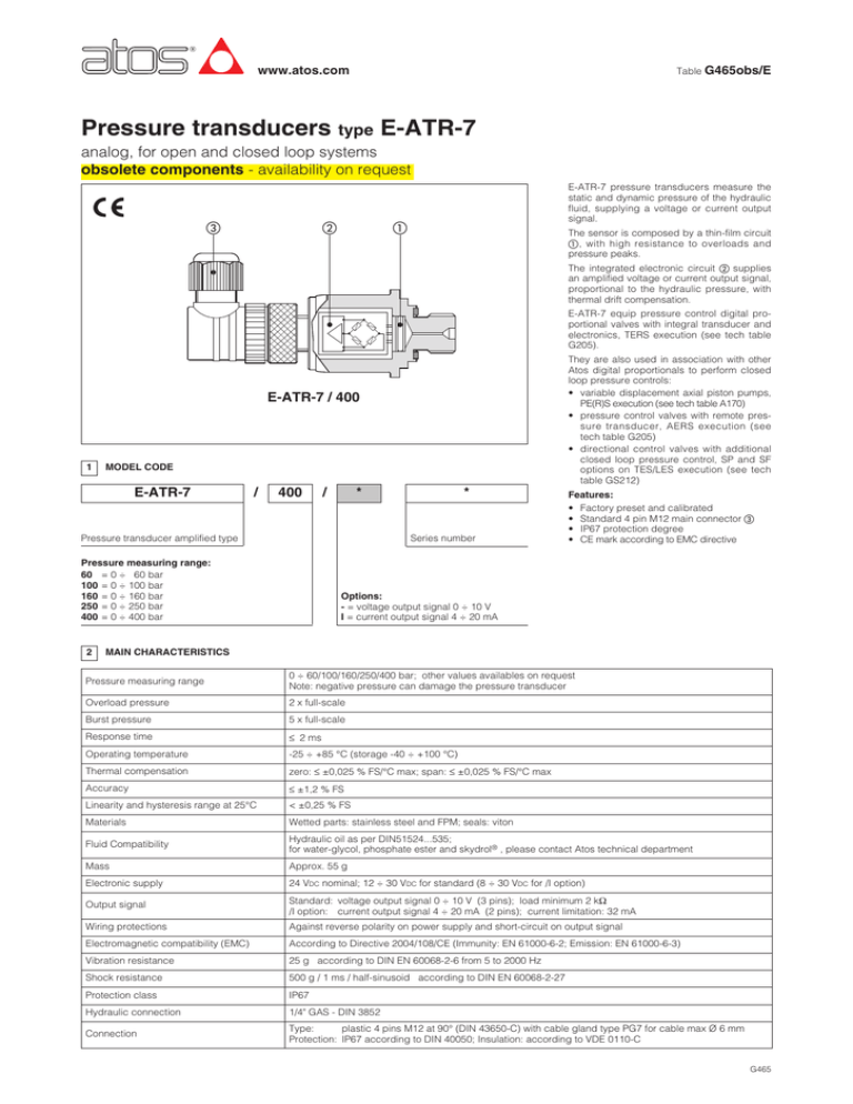
www.atos.com Table G465obs/E Pressure transducers type E-ATR-7 analog, for open and closed loop systems obsolete components - availability on request E-ATR-7 pressure transducers measure the static and dynamic pressure of the hydraulic fluid, supplying a voltage or current output signal. The sensor is composed by a thin-film circuit , with high resistance to overloads and pressure peaks. The integrated electronic circuit supplies an amplified voltage or current output signal, proportional to the hydraulic pressure, with thermal drift compensation. E-ATR-7 equip pressure control digital proportional valves with integral transducer and electronics, TERS execution (see tech table G205). They are also used in association with other Atos digital proportionals to perform closed loop pressure controls: • variable displacement axial piston pumps, PE(R)S execution (see tech table A170) • pressure control valves with remote pressure transducer, AERS execution (see tech table G205) • directional control valves with additional closed loop pressure control, SP and SF options on TES/LES execution (see tech table GS212) E-ATR-7 / 400 1 MODEL CODE E-ATR-7 / 400 / * Pressure transducer amplified type Series number Pressure measuring range: 60 = 0 ÷ 60 bar 100 = 0 ÷ 100 bar 160 = 0 ÷ 160 bar 250 = 0 ÷ 250 bar 400 = 0 ÷ 400 bar 2 * Features: • Factory preset and calibrated • Standard 4 pin M12 main connector • IP67 protection degree • CE mark according to EMC directive Options: - = voltage output signal 0 ÷ 10 V I = current output signal 4 ÷ 20 mA MAIN CHARACTERISTICS Pressure measuring range 0 ÷ 60/100/160/250/400 bar; other values availables on request Note: negative pressure can damage the pressure transducer Overload pressure 2 x full-scale Burst pressure 5 x full-scale Response time £ 2 ms Operating temperature -25 ÷ +85 °C (storage -40 ÷ +100 °C) Thermal compensation zero: £ ±0,025 % FS/°C max; span: £ ±0,025 % FS/°C max Accuracy £ ±1,2 % FS Linearity and hysteresis range at 25°C < ±0,25 % FS Materials Wetted parts: stainless steel and FPM; seals: viton Fluid Compatibility Hydraulic oil as per DIN51524...535; for water-glycol, phosphate ester and skydrol® , please contact Atos technical department Mass Approx. 55 g Electronic supply 24 VDC nominal; 12 ÷ 30 VDC for standard (8 ÷ 30 VDC for /I option) Output signal Standard: voltage output signal 0 ÷ 10 V (3 pins); load minimum 2 kW /I option: current output signal 4 ÷ 20 mA (2 pins); current limitation: 32 mA Wiring protections Against reverse polarity on power supply and short-circuit on output signal Electromagnetic compatibility (EMC) According to Directive 2004/108/CE (Immunity: EN 61000-6-2; Emission: EN 61000-6-3) Vibration resistance 25 g according to DIN EN 60068-2-6 from 5 to 2000 Hz Shock resistance 500 g / 1 ms / half-sinusoid according to DIN EN 60068-2-27 Protection class IP67 Hydraulic connection 1/4" GAS - DIN 3852 Connection Type: plastic 4 pins M12 at 90° (DIN 43650-C) with cable gland type PG7 for cable max Ø 6 mm Protection: IP67 according to DIN 40050; Insulation: according to VDE 0110-C G465 INSTALLATION AND COMMISSIONING 3 3.1 Warning E-ATR-7 transducers have to be installed as near as possible to the point where the pressure have to be measured, taking care that the oil flow is not turbulent. 3.2 Commissioning Install the transducer in the hydraulic circuit. Switch-off the power supply before connecting and disconnecting the transducer connector as shown in scheme 4 . 4 ELECTRONIC CONNECTIONS E-ATR-7 / * voltage output signal 0 ÷ 10 V USER CONNECTION EXAMPLE TRANSDUCER PINOUT 1 V+ Power supply (12 ÷ 30 VDC) 2 hydraulic pressure 3 V0 4 Vout Power supply (0 VDC) Signal E-ATR-7 / * / I current output signal 4 ÷ 20 mA USER CONNECTION EXAMPLE TRANSDUCER PINOUT 1 V+ Power supply (8 ÷ 30 VDC) 2 hydraulic pressure 3 Vout Signal 4 RL AGND The max resistance RL [W] is calculated: RL = 5 Vsupply –10[V] 0,02 [A] OVERALL DIMENSIONS [mm] ZBE-06 5.2 CH.27 17÷20 Nm G 1/4” Ø 18.8 Ø 29.5 27 2.9 transducer connector front view 11.9 33.4 ~ 37.1 ~ 82.4 05/16
