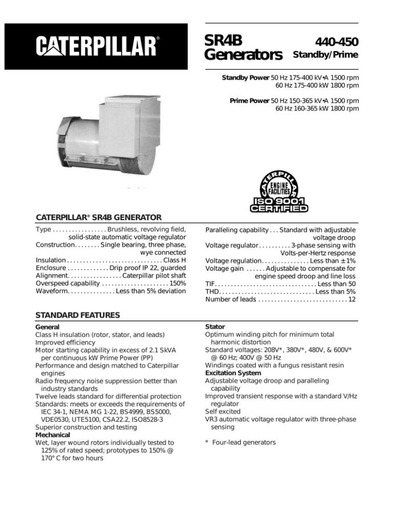
SR4B
Generators
440-450
Standby/Prime
Standby Power 50 Hz 175-400 kV•A 1500 rpm
60 Hz 175-400 kW 1800 rpm
Prime Power 50 Hz 150-365 kV•A 1500 rpm
60 Hz 160-365 kW 1800 rpm
CATERPILLAR® SR4B GENERATOR
Type . . . . . . . . . . . . . . . . . Brushless, revolving field,
..................solid-state automatic voltage regulator
Construction. . . . . . . . Single bearing, three phase,
. . . . . . . . . . . . . . . . . . . . . . . . . . . . . . . . wye connected
Insulation . . . . . . . . . . . . . . . . . . . . . . . . . . . . . . Class H
Enclosure . . . . . . . . . . . . . Drip proof IP 22, guarded
Alignment. . . . . . . . . . . . . . . . . Caterpillar pilot shaft
Overspeed capability . . . . . . . . . . . . . . . . . . . . . 150%
Waveform. . . . . . . . . . . . . . . Less than 5% deviation
Paralleling capability . . . Standard with adjustable
............................................................voltage droop
Voltage regulator . . . . . . . . . . 3-phase sensing with
..........................................Volts-per-Hertz response
Voltage regulation. . . . . . . . . . . . . . . Less than ± 1%
Voltage gain . . . . . . Adjustable to compensate for
...........................engine speed droop and line loss
TIF. . . . . . . . . . . . . . . . . . . . . . . . . . . . . . . . Less than 50
THD. . . . . . . . . . . . . . . . . . . . . . . . . . . . . . Less than 5%
Number of leads . . . . . . . . . . . . . . . . . . . . . . . . . . . . 12
STANDARD FEATURES
General
Class H insulation (rotor, stator, and leads)
Improved efficiency
Motor starting capability in excess of 2.1 SkVA
per continuous kW Prime Power (PP)
Performance and design matched to Caterpillar
engines
Radio frequency noise suppression better than
industry standards
Twelve leads standard for differential protection
Standards: meets or exceeds the requirements of
IEC 34-1, NEMA MG 1-22, BS4999, BS5000,
VDE0530, UTE5100, CSA22.2, ISO8528-3
Superior construction and testing
Mechanical
Wet, layer wound rotors individually tested to
125% of rated speed; prototypes to 150% @
170° C for two hours
Stator
Optimum winding pitch for minimum total
harmonic distortion
Standard voltages: 208V*, 380V*, 480V, & 600V*
@ 60 Hz; 400V @ 50 Hz
Windings coated with a fungus resistant resin
Excitation System
Adjustable voltage droop and paralleling
capability
Improved transient response with a standard V/Hz
regulator
Self excited
VR3 automatic voltage regulator with three-phase
sensing
* Four-lead generators
SR4B GENERATORS – 440-450 STANDBY/PRIME
OPTIONAL FEATURES
2/3 stator winding pitch
Bearing temperature detectors –
100Ω Pt or 10Ω Cu
Custom voltages
Manual voltage control
Generator mounted circuit breaker box
Paralleling kit with sensing and power isolation
transformers
RFI filter – 82/499/EEC, 89/336/EEC, German VDE
875/10.84 A2 Level N, British BS800 standards,
MIL-STD-461B and MIL-STD-461C (conducted,
radiated, and susceptibility)
Stator temperature detectors – Type J (ironconstantan) thermocouples
Separate compartment for low voltage wiring
connections
Terminal box extension with modular design
allowing RH or LH mount optimized for use with
or without circuit breakers
VR3F for enhanced transient response and
block loading
ROTOR CONSTRUCTION
MAIN STATOR CONSTRUCTION
The main rotor uses a precision “wet” layer
wound process, with epoxy painted on the bare
rotor and on each layer. This ensures bonding
of all the wire layers together, bonding of the
coils to the rotor laminations, and a sealed
insulation system. The rotor epoxy is then ovencured.
The exciter rotor is machine wound and receives
two dips and bakes of a fungus-resisting resin.
Numerically controlled turning and grinding
machines produce rotor shafts with close
repeatable tolerances. Grade-8 bolts are used
wherever joints are subject to induced stresses.
A complete coating of red sealer is applied to
protect the rotors and shaft from moisture
corrosion.
All rotor designs are prototype tested to 150%
of rated speed at 170° C for two hours without
any movement of material. Every production
rotor is dynamically balanced in two planes to
within 0.025 mm peak-to-peak amplitude and
run at 125% of rated speed before assembly into
the stator.
New square lamination stator design
Stator coil pitch, coil distribution, and skew are
designed to produce optimum waveform and
minimum total harmonic content.
Stator slots are insulated by slot liners and coil
separators. Slot liners, coil separators, and top
sticks provide a minimum of 25 mm (1 in)
distance from the coil to ground. The thickness
of liners, separators, and phase sheets provides
superior protection between phases and
ground.
Low voltage stator windings are given a 3000 volt
“high pot” test (150% of the NEMA and IEC
requirements for 480 volt generators) before the
insulation is applied. The stators are then given a
vacuum impregnation treatment of polyester
material followed by an application of epoxy
resin. This sealed stator is then given a final 2000
volt “high pot” test.
SR4B GENERATORS – 440-450 STANDBY/PRIME
Frame
Voltage
Ratings
130° C Rise
kV•A
kW
Eff (%)
443
400
444
400
50 Hz 1500 rpm – Standby
445
446
447
448
400
400
400
400
175
140
90.2
200
160
91.0
225
180
91.5
250
200
91.0
275
220
91.4
300
240
92.3
350
280
92.7
400
320
93.3
0.17250
0.16991
0.16095
0.16470
0.16638
0.14425
0.15429
0.16049
0.18904
0.18889
0.18150
0.18739
0.19111
0.16823
0.18214
0.19176
0.27311
0.27279
0.26201
0.27045
0.27574
0.24262
0.26259
0.27636
2.72549
2.77295
2.71072
2.82860
2.91648
2.61143
2.86493
3.05477
1.60555
1.63199
1.59398
1.66241
1.71313
1.53266
1.68038
1.79064
0.18077
0.17940
0.17123
0.17604
0.17875
0.15624
0.16821
0.17612
0.05149
0.04196
0.05134
0.05361
0.05532
0.04959
0.05446
0.05812
1.33008
1.40984
1.49384
1.54984
1.61144
1.71633
1.80584
1.90009
0.13328
0.13869
0.14439
0.14818
0.15235
0.15946
0.16552
0.17189
0.00778
0.00781
0.00783
0.00785
0.00786
0.00789
0.00791
0.00793
0.00325
0.00306
0.00285
0.00272
0.00257
0.00230
0.00209
0.00187
0.00709
0.00731
0.00755
0.00770
0.00787
0.00814
0.00837
0.00861
0.00043
0.00038
0.00032
0.00031
0.00028
0.00021
0.00020
0.00017
0.01722
0.01976
0.02063
0.01780
0.01889
0.02001
0.02198
0.02501
449
400
450
400
Reactances (per unit)
SubtransientDirect Axis
X"d
Subtransient
Quadrature Axis
X"q
Transient Saturated
X'd
Synchronous
Direct Axis
Xd
Synchronous
Quadrature Axis
Xq
Negative Sequence
X2
Zero Sequence
Xo
Time Constants (seconds)
Open Circuit
Transient Direct
Axis
T'do
Short Circuit
Transient Direct
Axis
T'd
Open Circuit
Subtransient
Direct Axis
T"do
Short Circuit
Subtransient
Direct Axis
T"d
Open Circuit
Subtransient
Quad Axis
T"qo
Short Circuit
Subtransient
Quad Axis
T"q
Armature
Ta
SR4B GENERATORS – 440-450 STANDBY/PRIME
Frame
Voltage
Ratings
130° C Rise
kV•A
kW
Eff (%)
443
480
444
480
60 Hz 1800 rpm – Standby
445
446
448
480
480
480
219
175
91.1
250
200
91.9
288
230
92.3
312
250
91.8
375
300
92.9
437
350
93.3
500
400
93.8
0.17968
0.17699
0.17139
0.17156
0.15026
0.16072
0.16718
0.19692
0.19676
0.19326
0.19520
0.17524
0.18973
0.19975
0.28449
0.28415
0.27899
0.28172
0.25273
0.27353
0.28787
2.83906
2.88849
2.88642
2.94646
2.72023
2.98430
3.18205
1.67245
1.69999
1.69729
1.73167
1.59652
1.75039
1.86525
0.18830
0.18688
0.18232
0.18338
0.16275
0.17522
0.18346
0.05363
0.05464
0.05467
0.05585
0.05166
0.05673
0.06054
1.33008
1.40984
1.49684
1.54984
1.71633
1.80584
1.90009
0.13328
0.13869
0.14439
0.14818
0.15946
0.16552
0.17189
0.00778
0.00781
0.00783
0.00785
0.00789
0.00791
0.00793
0.00272
0.00255
0.00238
0.00227
0.00192
0.00175
0.00156
0.00709
0.00731
0.00755
0.00770
0.00814
0.00837
0.00861
0.00037
0.00033
0.00029
0.00026
0.00018
0.00017
0.00015
0.01722
0.01976
0.02063
0.01780
0.02001
0.02198
0.02501
449
480
450
480
Reactances (per unit)
SubtransientDirect Axis
X"d
Subtransient
Quadrature Axis
X"q
Transient Saturated
X'd
Synchronous
Direct Axis
Xd
Synchronous
Quadrature Axis
Xq
Negative Sequence
X2
Zero Sequence
Xo
Time Constants (seconds)
Open Circuit
Transient Direct
Axis
T'do
Short Circuit
Transient Direct
Axis
T'd
Open Circuit
Subtransient
Direct Axis
T"do
Short Circuit
Subtransient
Direct Axis
T"d
Open Circuit
Subtransient
Quad Axis
T"qo
Short Circuit
Subtransient
Quad Axis
T"q
Armature
Ta
SR4B GENERATORS – 440-450 STANDBY/PRIME
Frame
Voltage
Ratings
130° C Rise
kV•A
kW
Eff (%)
443
400
445
400
50 Hz 1500 rpm – Prime
446
447
448
400
400
400
150
120
90.9
205
164
91.8
225
182
91.4
0.14785
0.14665
0.14823
0.15126 0.13223
0.14106
0.14645
0.16204
0.16536
0.16865
0.17374
0.15421
0.16653
0.17498
0.23409
0.23872
0.24340
0.25068
0.22240
0.24008
0.25217
2.33614
0.46977
2.54574
2.65135
2.39381
0.61936
2.78748
1.37619
1.45229
1.49617
1.55739
1.40494
1.53634
1.63396
0.15494
0.15601
0.15844
0.16250
1.14322
0.15380
0.16071
0.04413
0.04678
0.04825
0.05029
0.04546
0.04979
0.05303
1.33008
1.49384
1.54984
1.61144
1.71633
1.80584
1.90009
0.13328
0.14439
0.14818
0.15235
0.15946
0.16552
0.17189
0.00778
0.00783
0.00785
0.00786
0.00789
0.00791
0.00793
0.00322
0.00283
0.00270
0.00256
0.00229
0.00208
0.00186
0.00709
0.00755
0.00770
0.00787
0.00814
0.00837
0.00861
0.00037
0.00029
0.00027
0.00026
0.00019
0.00018
0.00016
0.01722
0.02063
0.01780
0.01889
0.02001
0.02198
0.02501
250
200
91.8
275
220
92.5
449
400
450
400
320
256
93.0
365
292
93.6
Reactances (per unit)
SubtransientDirect Axis
X"d
Subtransient
Quadrature Axis
X"q
Transient Saturated
X'd
Synchronous
Direct Axis
Xd
Synchronous
Quadrature Axis
Xq
Negative Sequence
X2
Zero Sequence
Xo
Time Constants (seconds)
Open Circuit
Transient Direct
Axis
T'do
Short Circuit
Transient Direct
Axis
T'd
Open Circuit
Subtransient
Direct Axis
T"do
Short Circuit
Subtransient
Direct Axis
T"d
Open Circuit
Subtransient
Quad Axis
T"qo
Short Circuit
Subtransient
Quad Axis
T"q
Armature
Ta
SR4B GENERATORS – 440-450 STANDBY/PRIME
Frame
Voltage
Ratings
130° C Rise
kV•A
kW
Eff (%)
443
480
60 Hz 1800 rpm – Prime
445
446
448
480
480
480
449
480
450
480
200
160
91.5
263
210
92.5
344
275
93.0
400
320
93.5
456
365
94.0
281
225
92.1
Reactances (per unit)
SubtransientDirect Axis
X"d
0.16428
0.15649
0.15440
0.13774
0.14694
0.15255
0.18004
0.17646
0.17568
0.16064
0.17347
0.18227
0.26010
0.25473
0.25354
0.23167
0.25009
0.26268
2.59571
2.63543
2.65181
2.49355
2.72850
2.90362
1.52910
1.54970
1.55851
1.46348
1.60036
1.70204
0.17216
0.16647
0.16504
0.14919
0.16020
0.16741
0.04903
0.04992
0.05026
0.04735
0.05186
0.05524
1.33008
1.49384
1.54984
1.71633
1.80584
1.90009
0.13328
0.14439
0.14818
0.15946
0.16552
0.17189
0.00778
0.00783
0.00785
0.00789
0.00791
0.00793
0.00270
0.00237
0.00226
0.00191
0.00174
0.00155
0.00709
0.00755
0.00770
0.00814
0.00837
0.00861
0.00034
0.00025
0.00024
0.00017
0.00015
0.00014
0.01722
0.02063
0.01780
0.02001
0.02198
0.02501
Subtransient
Quadrature Axis
X"q
Transient Saturated
X'd
Synchronous
Direct Axis
Xd
Synchronous
Quadrature Axis
Xq
Negative Sequence
X2
Zero Sequence
Xo
Time Constants (seconds)
Open Circuit
Transient Direct
Axis
T'do
Short Circuit
Transient Direct
Axis
T'd
Open Circuit
Subtransient
Direct Axis
T"do
Short Circuit
Subtransient
Direct Axis
T"d
Open Circuit
Subtransient
Quad Axis
T"qo
Short Circuit
Subtransient
Quad Axis
T"q
Armature
Ta
Materials and specifications are subject to change without notice.
LEHX6429
© 1996 Caterpillar Inc.
The International System of Units (SI) is used in this publication.
Printed in U.S.A.
All rights reserved.


