Spring 2002 - Spectrum Software
advertisement
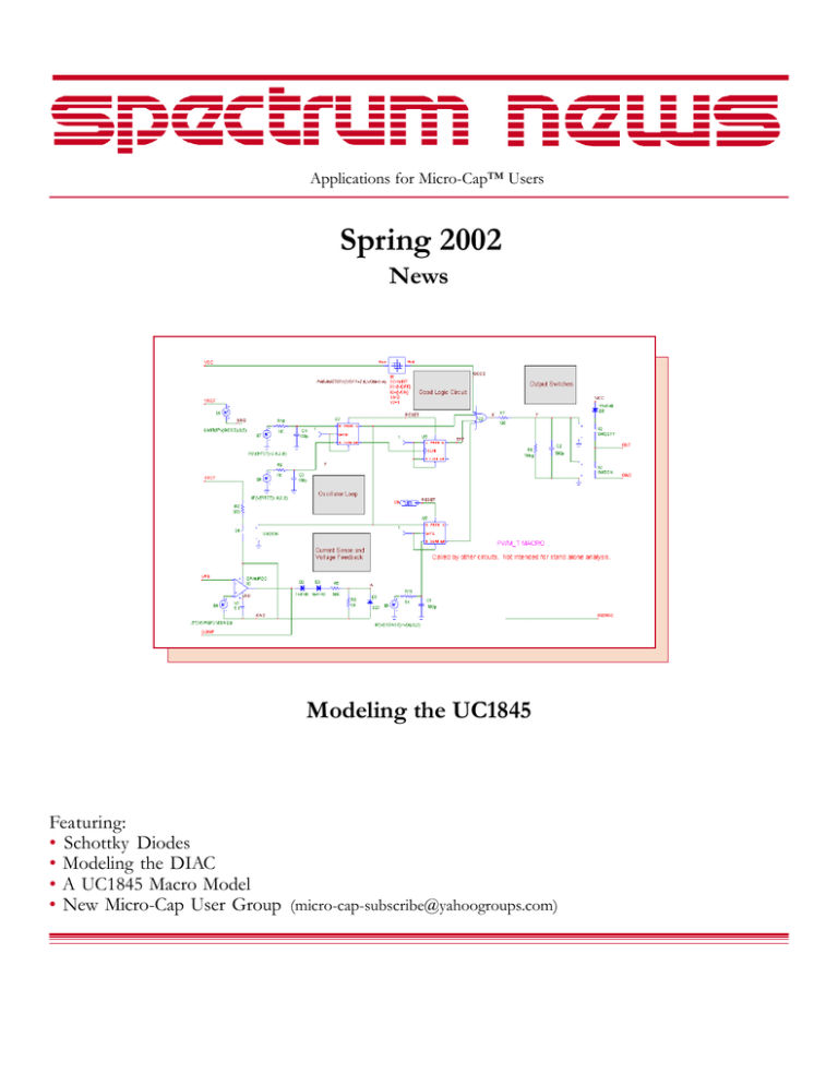
Applications for Micro-Cap™ Users Spring 2002 News Modeling the UC1845 Featuring: • Schottky Diodes • Modeling the DIAC • A UC1845 Macro Model • New Micro-Cap User Group (micro-cap-subscribe@yahoogroups.com) News In Preview This newsletter's Q and A section describes how avoid problems with the security key driver in Windows 2000, aligning cursors in analysis plots, and how to use the .DEFINE statement to implement useful math functions. The first article describes a method for modeling Schottky diodes and discusses the main differences between them and regular diodes. The second article describes a model for DIAC devices and illustrates how they can be used in TRIAC circuit applications such dimmer switches. The third article describes a model for the UC1845 PWM that is based on an excellent article that appeared recently in EDN magazine. The fourth article describes the new Micro-Cap User Group and how to join it. Contents News In Preview.............................................................................................................................................. 2 Book Recommendations ................................................................................................................................ 3 Micro-Cap Questions and Answers .............................................................................................................. 4 Easily Overlooked Features .......................................................................................................................... 5 Schottky Diodes .............................................................................................................................................. 6 Modeling the DIAC ....................................................................................................................................... 11 A UC1845 Macro Model .............................................................................................................................. 14 New Micro-Cap User Group ....................................................................................................................... 17 Product Sheet ................................................................................................................................................. 18 2 Book Recommendations Micro-Cap / SPICE • Computer-Aided Circuit Analysis Using SPICE, Walter Banzhaf, Prentice Hall 1989. ISBN# 0-13-162579-9 • Macromodeling with SPICE, Connelly and Choi, Prentice Hall 1992. ISBN# 0-13-544941-3 • Inside SPICE-Overcoming the Obstacles of Circuit Simulation, Ron Kielkowski, McGraw-Hill, First Edition, 1993. ISBN# 0-07-911525-X • The SPICE Book, Andrei Vladimirescu, John Wiley & Sons, Inc., First Edition, 1994. ISBN# 0-471-60926-9 MOSFET Modeling • MOSFET Models for SPICE Simulation, William Liu, Including BSIM3v3 and BSIM4, Wiley-Interscience, First Edition, ISBN# 0-471-39697-4 VLSI Design • Introduction to VLSI Circuits and Systems, John P. Uyemura, John Wiley & Sons Inc, First Edition, 2002 ISBN# 0-471-12704-3 German • Schaltungen erfolgreich simulieren mit Micro-Cap V, Walter Gunther, Franzis', First Edition, 1997. ISBN# 3-7723-4662-6 Design • Microelectronic CircuitsHigh Performance Audio Power Amplifiers, Ben Duncan, Newnes, First Edition, 1996. ISBN# 0-7506-2629-1 • Microelectronic Circuits., Adel Sedra, Kenneth Smith, Fourth Edition, Oxford, 1998 High Power Electronics • Power Electronics, Mohan, Undeland, Robbins, Second Edition, 1995. ISBN# 0-471-58408-8 • Modern Power Electronics, Trzynadlowski, 1998. ISBN# 0-471-15303-6 Switched-Mode Power Supply Simulation • SMPS Simulation with SPICE 3, Steven M. Sandler, McGraw Hill, First Edition, 1997. ISBN# 0-07-913227-8 • Switch-Mode Power Supply SPICE Simulation Cookbook, Christophe Basso, McGraw-Hill 2001. This book describes many of the SMPS models supplied with Micro-Cap. RF Electronics • Microwave Circuit Design, Vendelin, Pavio, and Rhoda, First Edition, 1990. ISBN# 0-471-60276-0 3 Micro-Cap Questions and Answers Question: I just installed Micro-Cap 7 on my Windows 2000 and when I run it I get an error message about not being able to find the key in the parallel port. I thought Micro-Cap 7 was supposed to run on Windows 2000. Answer: It does. The problem is probably in the settings for your parallel port. Check the settings under Control Panel / System / Hardware / Device Manager / Ports / Parallel Port. The setting should be ECP or BIDI. If it is set to Auto, then the Hasp key driver will not be able to recognize the key in the parallel port. Question: How do I get the cursors in one plot to align with the cursors in another plot? They used to be lined up but I can't get then to align anymore. Is there an option somewhere? Answer: Enable the Align Cursors on the Scope menu after the plot is drawn. This option is saved in the circuit file and is on by default for newly created circuits. Question: Can I make a function in Micro-Cap as you can in the C language? Answer: Yes you can. User functions are implemented as an extension of the .DEFINE command. The normal usage of the .DEFINE command is as follows: .DEFINE RDIM 250K This simply defines a constant RDIM that can be used elsewhere in the circuit. The other usage of the command lets you define useful functions like this: .DEFINE QUADRATIC(A,B,C) ((-B+SQRT(B*B-4*A*C))/(2*A)) Then you might call it with circuit variables or constants like this QUADRATIC(V(10), 21.34, V(3,14)) These functions can be made available to all circuits by placing them in the User Definitions file ( Options menu / User Definitions ) or can be kept local to the current circuit by placing them in the circuit's text area or schematic grid text. 4 Easily Overlooked Features This section is designed to highlight one or two features per issue that may be overlooked because they are not made visually obvious with an icon or a menu item. Rubberbanding If you've ever tried to clean up a messy schematic, or add a section of circuitry between two closely spaced sections, you'll understand the value of rubberbanding. It lets you drag a section of circuitry while maintaining the nodal connections. Rubberbanding mode is toggled on and off from Preferences / Common Options / Circuit / Rubberbanding. Inevitably, when using the feature, you reach a point where you want to move a block of circuitry without dragging the lines. To do this you turn rubberbanding off. But its a pain to navigate through the menus to do so. Well, there's no need to. SHIFT+CTRL+R will toggle the rubbberbanding state from On to Off or from Off to On. One further tip, when using ruberbanding mode, is to define a box region and then drag it, as opposed to dragging individual parts. This avoids diagonal wires. Status Bar Display If the Status Bar display is enabled (Options menu / Status Bar), moving the mouse cursor over a component will show useful information about the part, like its name, type, its most recent timedomain current and power terms and its condition (On, Off, Sat, Lin, etc.) Attribute dialog box Plot command If you haven't yet used the Micro-Cap 7 ADB Plot option, you're missing a good thing. It makes a plot of the part's characteristic curve. This is particularly useful for waveform sources. The plot dynamically responds as you change the source parameters, so you can see their effect immediately. Its useful for other primitives as well, like diodes, NPNs, and other active devices. It lets you visualize and appreciate the impact their parameters have on the principle characteristic curves. 5 Schottky Diodes A Schottky-barrier diode is fabricated by applying a metal contact to a moderately-doped n-type region. The underlying material can be silicon, or gallium-arsenide. The junction produced by the metal, which behaves like a lightly-doped p-type material, and the moderately-doped n-type material, is a rectifying diode-like contact. It differs from ordinary diode junctions in two important ways: Switching is faster The Schottky diode achieves current transport by movement of majority carriers, as opposed to normal diodes, which employ minority carriers. This produces a very fast diode due to the drastic reduction in the usual charge storage effects associated with minority carriers. Voltage drop is lower The forward drop of the Schottky diode is much smaller than that of normal diodes, being on the order of 0.3v to 0.5v for silicon and around .7v for gallium-arsenide Schottky diodes. Modeling a Schottky diode is done using the standard diode primitive. The main objectives are to match the low forward I-V characteristic and the fast switching time. The normal forward drop of the diode with typical parameters is about 0.7 volts for currents in the 10m to 100ma range. In a Schottky diode the drop will be somewhat lower. Typically the forward drop is around .3 to .5 volts. To achieve the lower drop you can increase the diode IS model parameter value from its typical value of 1E-15 to as high as 1E-9. The larger the IS the smaller the forward drop. To illustrate the effect of the IS parameter, consider the following test circuit. Fig. 1- SBD test circuit This circuit contains a current source which drives the diode under test to display the forward characteristic in DC analysis. It also is programmed to emit a current pulse in transient analysis to display the transit time delay. The diode's IS is set to 1n, its N is set to .5, and its TT is set to 10p. 6 Select DC analysis from the Run menu. The DC analysis limits look like this: Fig. 2- DC analysis limits for creating the I-V curve These analysis limits are set to logarithmically sweep the current source from 1pa to 100ma. The log step factor of 1.5 means to multiply each value of I1 by 1.5 until the final value of 1e-10 is achieved. The expression fields are set up to plot the diode's current versus its voltage so that we can see the diode's forward IV curve. Fig. 3- Stepping dialog settings for stepping the IS parameter Here is the Stepping dialog box. It specifies that we are to step the diode's IS parameter from 1E14 to 1E-10. For each value of IS one complete DC analysis sweep will be done producing one IV curve, so we can see the effect of the IS parameter on the diode's forward characteristic. 7 This is what the run looks like: Fig. 4- Diode IV curve for IS=10f to 100p You can achieve a similar curve by reducing the N value and using a normal (1E-15) value for IS. Here is an example where the IS parameter is set to 1E-15 and N is varied from .3 to .5 resulting in a forward drop in the same range. Here the diode forward drop at 50ma varies from 250mv at N=.3 to about 420mv when N=.5 Fig. 5- Diode IV curve for N=.3 to .5 8 To illustrate how to measure the TT time, we'll run transient analysis on this circuit. The pulse source has been set up to produce a forward biasing current, then a reverse biasing current and we are interested in the time it takes the diode to come out of forward bias. Here are the transient analysis limits. Fig. 6- Transient analysis limits for plotting the diode voltage These analysis limits are set to plot the source current and the diode voltage so that we can measure the reverse transit time. Fig.7- Stepping dialog settings for stepping the TT parameter Here is the Stepping dialog box. It specifies that we are to step the diode's IS TT linearly from 100P to 500p. For each value of TT one complete transient analysis run will be done producing one plot of the diode voltage, so we can see the effect of the TT parameter on the diode's reverse transit time. 9 This is what the run looks like: Fig. 8- Diode IV curve for IS=10f to 100p The plot shows that for the case of a 1u forward and 1u reverse current pulse, the reverse transit time is about 2/3 of the TT parameter. Estimating the necessary TT value then is fairly easy. For Schottky diodes, the reverse transit time is usually from 100p to 500p, so setting the TT value to half this value is a good quick approximation. 10 Modeling the DIAC A DIAC is a four-layer bidirectional trigger device that is designed to turn on an SCR or a TRIAC. It is similar to a TRIAC except that there is no gate pin to control the breakover voltage as there is in a TRIAC. Here is a macro model of the DIAC. Fig. 9- DIAC macro model The model has two parameters. VK specifies the breakover voltage at which the DIAC begins to conduct. RS specifies the limiting series resistance of the device. In the test circuit below, transient analysis steps the breakover voltage passed to the macro as a parameter and plots the resulting DIAC's characteristic IV curve for the four VK values, 20, 30, and 40 volts. Fig. 10- A circuit to plot the DIAC characteristic curve 11 Here is the characteristic curve of the DIAC curve with the VK (BREAKOVER) parameter stepped from 20 to 40 volts. Fig. 11- DIAC characteristic curves for VK = 20, 30, and 40 volts Here is a typical application of the DIAC: symmetrically triggering a TRIAC in a dimmer circuit. Fig. 12- A dimmer circuit using the DIAC macro model 12 Here is what the transient analysis of the circuit looks like when the dimmer pot is varied over its resistance range from almost zero to 450K. The last curve is a plot of the average power dissipated in the load resistor. The ending value approximates the steady state power delivered to the load. Fig. 13- Plot of power dissipated in the resistive load The performance plot below shows an approximation of the power dissipated in RL. It is an approximation because of the finite number of cycles used to compute the average. The plot shows that the maximum power occurs when RDIM is at zero and the full voltage is applied. The power trails off in a nonlinear fashion to zero at RDIM = 400K. Fig. 14- Performance plot showing load power vs. pot resistance 13 A UC1845 Macro Model A recent article in the March 7, 2002 issue of EDN, entitled "Modular macromodeling techniques for SPICE simulators", illustrated a very workable model for the UC1845 Pulse width modulator. We have implemented the model in Micro-Cap and expanded it to model the full line of UCX84X PWMs. This article describes the details. Altogether, twelve parts are modeled: UC1842, UC1843, UC1844, UC1845 UC2842, UC2843, UC2844, UC2845 UC3842, UC3843, UC3844, UC3845 The three UCX84X families are similar. Within each series, the UCXX44 and UCXX45 use an internal T flip-flop to divide down the internal oscillator to provide for differing duty cycles, while the others do not. The UCX842 and UCX844 sets the acceptable VCC range at 10-16 volts while the UCX843 and UCX845 have the acceptable VCC range set at 7.6-8.4 volts. Two basic macros are used to implement the entire line of parts, the PWM_T and the PWM_NT. Here is the PWM_T macro which uses the T Flip-flop. Fig. 15- The PWM_T macro The Good Logic section uses the Schmitt macro to produce a logic 1 when the VCC line has the desired voltage range. This signal is provided to the external pin and also enables the output switches. 14 Here is its twin, the PWM_NT. The only difference is the absence of the T Flip-flop. Fig. 16- The PWM_NT macro Here is the boost regulator test circuit from the EDN article. The circuit has been elaborated a little to add a pulse source on the VCC line to test the model's response to changes in the VCC line voltage. Fig. 17- Boost regulator test circuit 15 Here is the transient analysis of the circuit, showing the regulated output and the shutdown of regulation when the VCC voltage goes out of bounds, along with the Good VCC signal. Fig. 18- Transient response of the boost regulator test circuit This circuit and the appropriate macros are available for download from the Files section of the Micro-Cap User group. If you are not already a member, sign up now. 16 New Micro-Cap User Group Spectrum Software recently started a new user group dedicated to Micro-Cap users. It is designed to provide a public forum for questions and answers on how to use and get the most of the MicroCap program. You can sign up by emailing this address: micro-cap-subscribe@yahoogroups.com Although the group's purpose is to provide a forum for technical questions about Micro-Cap, it can also serve to help users learn advanced simulation and modeling techniques by taking advantage of the learning and knowledge already out there in the minds of our many experienced users. We have often been amazed at the resourcefulness of these engineers and scientists, especially in the many clever program suggestions they make. We are hoping that the user group will bring this useful technical resource to a larger community of users. 17 Product Sheet Latest Version numbers Micro-Cap 7 ....................................................................... Version 7.14 Micro-Cap 6 ....................................................................... Version 6.32 Micro-Cap V ...................................................................... Version 2.1.2 Spectrum’s numbers Sales .................................................................................... (408) 738-4387 Technical Support ............................................................ (408) 738-4389 FAX .................................................................................... (408) 738-4702 Email sales ......................................................................... sales@spectrum-soft.com Email support .................................................................... support@spectrum-soft.com Web Site ............................................................................. http://www.spectrum-soft.com User Group ........................................................................ micro-cap-subscribe@yahoogroups.com 18

