Lect 39
advertisement

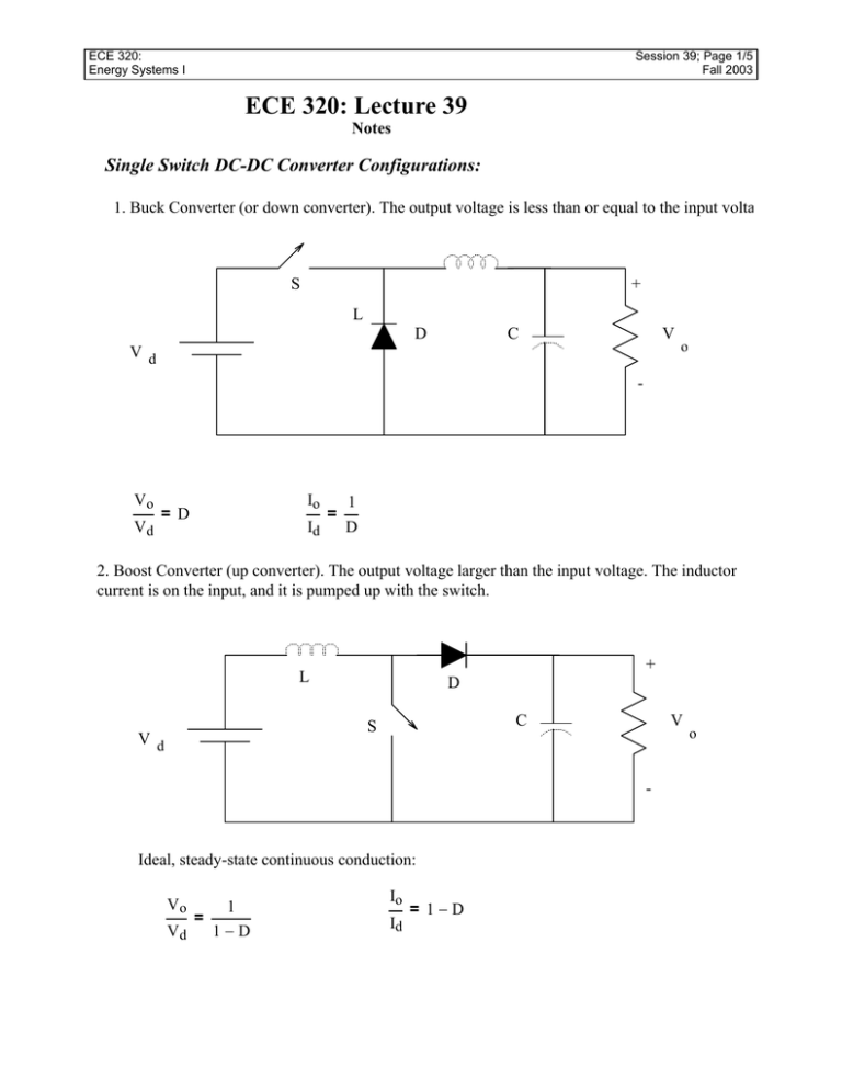
ECE 320: Energy Systems I Session 39; Page 1/5 Fall 2003 ECE 320: Lecture 39 Notes Single Switch DC-DC Converter Configurations: 1. Buck Converter (or down converter). The output voltage is less than or equal to the input volta S + L D V C Vd o - Vo Vd = D Io Id = 1 D 2. Boost Converter (up converter). The output voltage larger than the input voltage. The inductor current is on the input, and it is pumped up with the switch. + L D C S Vd V - Ideal, steady-state continuous conduction: Vo 1 = Vd 1−D Io Id = 1−D o ECE 320: Energy Systems I Session 39; Page 2/5 Fall 2003 3. Buck-Boost Converter (up/down converter). The output voltage can be smaller or larger than the input voltage. The inductor current is now an intermediate stage. Note output voltage polarity S - D L V C Vd o + Ideal, steady-state continuous conduction: Vo Vd = D 1−D Io Id = ( 1 − D) D Polarity of the voltage and the current is reversed from the other two topologies. Boundary of Discontinuous Conduction Through The Inductor: • Boost Converter When switch is closed, the slope of the inductor current is: : ∆iL t = Vd L When the switch is open, the slope is: ∆iL t = Vd − Vo L Since the current follows these slopes while the switch position is maintained, in continuous counduction the steady-state Current Ripple in inductor is: ∆iL = Vd ( Vd − Vo) ⋅ D ⋅ Ts = ⋅ ( 1 − D ) ⋅ Ts L L The average input current is now the average current through the inductor ECE 320: Energy Systems I Session 39; Page 3/5 Fall 2003 Power Balance: Po = Vo R 2 Vo and Vd = 1 1−D So: Vd Po = 2 2 ( 1 − D) ⋅ R But: Po = Pi = Vd⋅ ILave Vd Therefore: 2 2 ( 1 − D) ⋅ R = Vd⋅ ILave or ILave = Vd 2 ( 1 − D) ⋅ R Adding on the current ripple, the minimum current through the inductor is: ILmin = ILave − ∆iL 2 Adding on the current ripple, the maximum current through the inductor is: ILmax = ILave + ∆iL 2 At the boundary of discontinuous conduction we see: ILmin = 0 = Vd 2 ( 1 − D) ⋅ R Vd ⋅ D ⋅ Ts 2⋅ L − So, we can determine Lmin by solving this equation for L: 2 Lmin = D ⋅ ( 1 − D ) ⋅ R ⋅ Ts 2 ECE 320: Energy Systems I Session 39; Page 4/5 Fall 2003 We can also state this in terms of voltages and currents using: Vo Io R= IoB = ( 1 − D) ⋅ Id = ( 1 − D) ⋅ ILB 2 Lmin = D⋅ ( 1 − D) ⋅ Vo⋅ Ts 2⋅ IoB = D⋅ ( 1 − D) ⋅ Vo⋅ Ts 2⋅ ILB or in terms of the output current at the boundary: 2 D⋅ ( 1 − D) ⋅ Vo⋅ Ts IoB = • 2⋅ Lmin Buck-Boost Converter When switch is closed, the slope of the inductor current is: : ∆iL t = Vd L When the switch is open, the slope is: ∆iL t = Vo L Since the current follows these slopes while the switch position is maintained, in continuous counduction the steady-state Current Ripple in inductor is: ∆il = Vd ( −Vo) ⋅ D ⋅ Ts = ⋅ ( 1 − D ) ⋅ Ts L L Now the inductor current isn't the input current or the output current. It is only an intermediate step • At the boundary between continuous and discontinuous conduction, we will have: ILB = ∆iL 1 1 ⋅ ILpeak = = ⋅ D⋅ Ts⋅ Vd 2 2 2⋅ L ECE 320: Energy Systems I Session 39; Page 5/5 Fall 2003 or we could also write this in terms of Vo as: 1 1 − D 1 ILB = ⋅ D⋅ Ts⋅ ⋅ Vo = ⋅ Ts⋅ ( 1 − D) ⋅ Vo 2⋅ L D 2⋅ L or Lmin = 1 ⋅ Ts⋅ ( 1 − D) ⋅ Vo 2 ⋅ I LB However we usually want this in terms of the output current. If we write a node equation at the terminal of the inductor Io = IL − Id or D 1 − D + D Io = Io = 1 − D 1−D 1−D IL = Io + Id = Io + Io⋅ 1 ILB( 1 − D) = ⋅ Ts⋅ ( 1 − D) ⋅ Vo ⋅ ( 1 − D) 2⋅ L Vo 2 IoB = ⋅ Ts⋅ ( 1 − D) 2⋅ L Uncontrolled Rectifier Circuits (Chapter 5) • • • • • We have discussed the use of DC-DC converters to regulate a dc voltage to level different tha the input dc voltage. But we haven't discussed where this dc voltage comes from. In most applications we start with the 120Vrms from a wall outlet Now we want to convert that dc with a rectifier circuit Next week we will combine the rectifier with a transformer and a dc-dc converter in one circu


