Note: New design of a cryogenic linear radio frequency multipole trap
advertisement

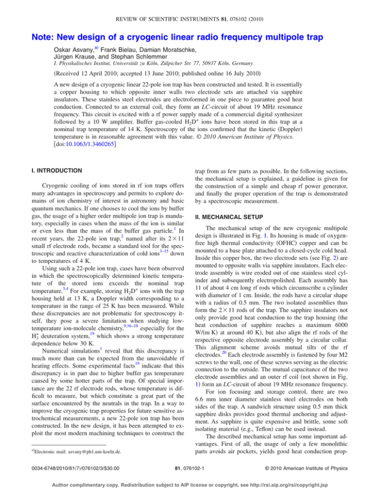
REVIEW OF SCIENTIFIC INSTRUMENTS 81, 076102 共2010兲 Note: New design of a cryogenic linear radio frequency multipole trap Oskar Asvany,a兲 Frank Bielau, Damian Moratschke, Jürgen Krause, and Stephan Schlemmer I. Physikalisches Institut, Universität zu Köln, Zülpicher Str. 77, 50937 Köln, Germany 共Received 12 April 2010; accepted 13 June 2010; published online 16 July 2010兲 A new design of a cryogenic linear 22-pole ion trap has been constructed and tested. It is essentially a copper housing to which opposite inner walls two electrode sets are attached via sapphire insulators. These stainless steel electrodes are electroformed in one piece to guarantee good heat conduction. Connected to an external coil, they form an LC-circuit of about 19 MHz resonance frequency. This circuit is excited with a rf power supply made of a commercial digital synthesizer followed by a 10 W amplifier. Buffer gas-cooled H2D+ ions have been stored in this trap at a nominal trap temperature of 14 K. Spectroscopy of the ions confirmed that the kinetic 共Doppler兲 temperature is in reasonable agreement with this value. © 2010 American Institute of Physics. 关doi:10.1063/1.3460265兴 I. INTRODUCTION Cryogenic cooling of ions stored in rf ion traps offers many advantages in spectroscopy and permits to explore domains of ion chemistry of interest in astronomy and basic quantum mechanics. If one chooses to cool the ions by buffer gas, the usage of a higher order multipole ion trap is mandatory, especially in cases when the mass of the ion is similar or even less than the mass of the buffer gas particle.1 In recent years, the 22-pole ion trap,2 named after its 2 ⫻ 11 small rf electrode rods, became a standard tool for the spectroscopic and reactive characterization of cold ions3–15 down to temperatures of 4 K. Using such a 22-pole ion trap, cases have been observed in which the spectroscopically determined kinetic temperature of the stored ions exceeds the nominal trap temperature.3,4 For example, storing H2D+ ions with the trap housing held at 13 K, a Doppler width corresponding to a temperature in the range of 25 K has been measured. While these discrepancies are not problematic for spectroscopy itself, they pose a severe limitation when studying lowtemperature ion-molecule chemistry,9,16–18 especially for the H+3 deuteration system,19 which shows a strong temperature dependence below 30 K. Numerical simulations1 reveal that this discrepancy is much more than can be expected from the unavoidable rf heating effects. Some experimental facts19 indicate that this discrepancy is in part due to higher buffer gas temperature caused by some hotter parts of the trap. Of special importance are the 22 rf electrode rods, whose temperature is difficult to measure, but which constitute a great part of the surface encountered by the neutrals in the trap. In a way to improve the cryogenic trap properties for future sensitive astrochemical measurements, a new 22-pole ion trap has been constructed. In the new design, it has been attempted to exploit the most modern machining techniques to construct the a兲 Electronic mail: asvany@ph1.uni-koeln.de. 0034-6748/2010/81共7兲/076102/3/$30.00 trap from as few parts as possible. In the following sections, the mechanical setup is explained, a guideline is given for the construction of a simple and cheap rf power generator, and finally the proper operation of the trap is demonstrated by a spectroscopic measurement. II. MECHANICAL SETUP The mechanical setup of the new cryogenic multipole design is illustrated in Fig. 1. Its housing is made of oxygenfree high thermal conductivity 共OFHC兲 copper and can be mounted to a base plate attached to a closed-cycle cold head. Inside this copper box, the two electrode sets 共see Fig. 2兲 are mounted to opposite walls via sapphire insulators. Each electrode assembly is wire eroded out of one stainless steel cylinder and subsequently electropolished. Each assembly has 11 of about 4 cm long rf rods which circumscribe a cylinder with diameter of 1 cm. Inside, the rods have a circular shape with a radius of 0.5 mm. The two isolated assemblies thus form the 2 ⫻ 11 rods of the trap. The sapphire insulators not only provide good heat conduction to the trap housing 共the heat conduction of sapphire reaches a maximum 6000 W/共m K兲 at around 40 K兲, but also align the rf rods of the respective opposite electrode assembly by a circular collar. This alignment scheme avoids mutual tilts of the rf electrodes.20 Each electrode assembly is fastened by four M2 screws to the wall, one of these screws serving as the electric connection to the outside. The mutual capacitance of the two electrode assemblies and an outer rf coil 共not shown in Fig. 1兲 form an LC-circuit of about 19 MHz resonance frequency. For ion focusing and storage control, there are two 6.6 mm inner diameter stainless steel electrodes on both sides of the trap. A sandwich structure using 0.5 mm thick sapphire disks provides good thermal anchoring and adjustment. As sapphire is quite expensive and brittle, some soft isolating material 共e.g., Teflon兲 can be used instead. The described mechanical setup has some important advantages. First of all, the usage of only a few monolithic parts avoids air pockets, yields good heat conduction prop- 81, 076102-1 © 2010 American Institute of Physics Author complimentary copy. Redistribution subject to AIP license or copyright, see http://rsi.aip.org/rsi/copyright.jsp 076102-2 Rev. Sci. Instrum. 81, 076102 共2010兲 Asvany et al. 490 H3+ counts 470 450 430 410 6466.51 6466.53 6466.55 -1 wavenumber / cm FIG. 1. 共Color online兲 Mechanical setup of the new 22-pole trap. It consists of a OFHC copper housing, sapphire insulators and stainless steel electrodes. FIG. 3. 共Color online兲 LIR-spectrum of cold stored H2D+ ions. The line shown is due to the rovibrational transition 111 ← 000 in the 共0,2,1兲 overtone band 共Ref. 4兲. The laser light with a power of 1.3 mW has been provided by a Agilent laser module 81600B. The Doppler profile indicates a kinetic temperature of about 共21⫾ 1兲 K. erties, results in little surface for good vacuum performance, and permits easy maintenance. Indium has not been used in the setup, allowing thus easily for high temperature applications. The electrode assemblies are fully enclosed in the copper box, leading to low rf stray fields. This makes temperature measurements of the copper housing via Si-diodes possible while the rf is applied, a feature which has been difficult in the former design.2 power of 10 W. The modern Mitsubishi VMOS 共vertical metal oxide semiconductor兲 transistors in push-pull configuration allow us to use this amplifier in the frequency range of 1.8–54 MHz. Tests have shown 共see below兲 that actually only a fraction of the power is needed to store cold ions, typically less than 0.5 W. III. HOME-MADE rf POWER SUPPLY IV. TEMPERATURE TESTS For the inductive excitation of the LC-circuit of the trap, a rf power supply tunable in a frequency range around 19 MHz is required, with an output power of a few watts. The home-made rf power supply has been assembled from parts which are commercially available. As the oscillator a 20 MHz direct digital synthesis board has been chosen. In such a synthesizer, the sinus signal is produced by digital-analog conversion and a subsequent low-pass filter. The output signal is tunable up to 20 MHz in 1 Hz steps and has a maximum output power of 56 mW. This signal is then amplified by a broadband amplifier QRP-PA-2008 up to a maximum As the 22-pole rods present a big surface to the cooling buffer gas, it is important to know how well they are thermally anchored to the trap housing. Therefore, several cooling tests 共with and without applying rf兲 have been performed with Si-diode temperature sensors attached to the copper housing and to the base of one rod assembly 共seen in Fig. 2兲. With the copper housing cooled to the lowest accessible temperature 共about 14 K兲, the rods showed a temperature which was at maximum 1.5 K higher. To test how well this ambient temperature transfers to the kinetic ion temperature via He buffer gas collisions, about 2000 H2D+ ions have been stored for 1 s in the trap, with a He collision rate of about 10 000/s. Due to the low temperatures, a forward rf power less than 0.2 W was sufficient for ion trapping in the current setup. The kinetic ion temperature has been determined via the Doppler width of spectroscopic measurements. For spectroscopy, the laser induced reaction 共LIR兲 共for details, see Refs. 3, 4, and 17兲, H2D+ + H2 + h → H+3 + HD, FIG. 2. 共Color online兲 Photo of the wire eroded and electropolished rod assembly. 共1兲 has been applied. A typical LIR-spectrum, in which the H+3 product ions of reaction 共1兲 are counted as a function of the laser frequency, is shown in Fig. 3. In order to avoid saturation effects, a relatively low laser power of 1.3 mW has been used. The FWHM of the LIR-signal is about 0.0106 cm−1 at a center frequency of 6466.532 cm−1, corresponding to a kinetic temperature of 21 K. Author complimentary copy. Redistribution subject to AIP license or copyright, see http://rsi.aip.org/rsi/copyright.jsp 076102-3 Rev. Sci. Instrum. 81, 076102 共2010兲 Asvany et al. V. DISCUSSION While the kinetic ion temperature measured with the new trap design is lower than in previous experiments4 using the former trap design,2 there is still a temperature difference between nominal and spectroscopic temperature of about 7 K in the present case. As shown by numerical simulations,1 a part of this difference in the range of 3 K is unavoidable and due to rf heating effects of a perfect trap. It is difficult to speculate about other heating effects, like those caused by insulating patches or low frequency noise on the involved electrodes, or some effects just contributing to the broadening of the line shown in Fig. 3, possibilities including laser jitter or incomplete emptying of the trap between trap fillings. Further investigations will help to clarify this. In the original 22-pole trap design,2 the multipolarity has been chosen due to the usage of 1 mm diameter syringe needles for the rods and the following geometrical constraints.21 The current design adopted the same multipolarity for simplicity and easy comparison, but modern machining methods will allow for higher multipolarities or even different electrode geometries. A multipole trap with more than 22 rods can be easily manufactured, though this will not substantially help in lowering the ion temperature. ACKNOWLEDGMENTS All parts of the trap have been machined by the mechanical workshop of the I. Physikalisches Institut at Köln University, except the sapphire insulators 共GWI Industriesaphire, Germany兲 and the rod assemblies 共Götz Funkenerosion, Germany兲. O.A. thanks Michael Weidner from Götz Funkenerosion for their excellent customer support. O.A. and S.S. thank Dieter Gerlich 共TU Chemnitz, Germany兲 for contributing parts for the test setup. Frank Lewen has helped in the project by gold coating the inducting coils of the trap setup. This work has been financially supported by the Deutsche Forschungsgemeinschaft 共DFG兲 via Grant No. SCHL 341/6-1. O. Asvany and S. Schlemmer, Int. J. Mass. Spectrom. 279, 147 共2009兲. D. Gerlich, Phys. Scr. T59, 256 共1995兲. 3 O. Asvany, O. Ricken, H. S. P. Müller, M. C. Wiedner, T. Giesen, and S. Schlemmer, Phys. Rev. Lett. 100, 233004 共2008兲. 4 O. Asvany, E. Hugo, F. Müller, F. Kühnemann, S. Schiller, J. Tennyson, and S. Schlemmer, J. Chem. Phys. 127, 154317 共2007兲. 5 O. Asvany, P. Padma Kumar, B. Redlich, I. Hegemann, S. Schlemmer, and D. Marx, Science 309, 1219 共2005兲. 6 A. Wolf, H. Kreckel, L. Lammich, D. Strasser, J. Mikosch, J. Glosík, R. Plašil, S. Altevogt, V. Andrianarijaona, H. Buhr, J. Hoffmann, M. Lestinsky, I. Nevo, S. Novotny, D. A. Orlov, H. B. Pedersen, A. S. Terekhov, J. Toker, R. Wester, D. Gerlich, D. Schwalm, and D. Zajfman, Philos. Trans. R. Soc. London, Ser. A 364, 2981 共2006兲. 7 J. Mikosch, H. Kreckel, R. Wester, R. Plašil, J. Glosík, D. Gerlich, D. Schwalm, and A. Wolf, J. Chem. Phys. 121, 11030 共2004兲. 8 S. Trippel, J. Mikosch, R. Berhane, R. Otto, M. Weidemüller, and R. Wester, Phys. Rev. Lett. 97, 193003 共2006兲. 9 R. Otto, J. Mikosch, S. Trippel, M. Weidemüller, and R. Wester, Phys. Rev. Lett. 101, 063201 共2008兲. 10 O. V. Boyarkin, S. R. Mercier, A. Kamariotis, and T. R. Rizzo, J. Am. Chem. Soc. 128, 2816 共2006兲. 11 A. Dzhonson, D. Gerlich, E. J. Bieske, and J. P. Maier, J. Mol. Struct. 795, 93 共2006兲. 12 I. Savić and D. Gerlich, Phys. Chem. Chem. Phys. 7, 1026 共2005兲. 13 Y.-S. Wang, C.-H. Tsai, Y. T. Lee, H.-C. Chang, J. C. Jiang, O. Asvany, S. Schlemmer, and D. Gerlich, J. Phys. Chem. A 107, 4217 共2003兲. 14 H. Kreckel, D. Bing, S. Reinhardt, A. Petrignani, M. Berg, and A. Wolf, J. Chem. Phys. 129, 164312 共2008兲. 15 S. D. Ivanov, O. Asvany, A. Witt, E. Hugo, G. Mathias, B. Redlich, D. Marx, and S. Schlemmer, Nat. Chem. 2, 298 共2010兲. 16 D. Gerlich, E. Herbst, and E. Roueff, Planet. Space Sci. 50, 1275 共2002兲. 17 S. Schlemmer, O. Asvany, E. Hugo, and D. Gerlich, in IAU Symposium 231, edited by D. Lis, G. Blake, and E. Herbst 共Cambridge University Press, Asilomar, CA, 2006兲. 18 O. Asvany, S. Schlemmer, and D. Gerlich, Astrophys. J. 617, 685 共2004兲. 19 E. Hugo, O. Asvany, and S. Schlemmer, J. Chem. Phys. 130, 164302 共2009兲. 20 R. Otto, P. Hlavenka, S. Trippel, J. Mikosch, K. Singer, M. Weidemüller, and R. Wester, J. Phys. B 42, 154007 共2009兲. 21 D. Gerlich, in Adv. Chem. Phys.: State-Selected and State-to-State IonMolecule Reaction Dynamics, edited by C.-Y. Ng and M. Baer 共Wiley, New York, 1992兲, Vol. LXXXII, pp. 1–176. 1 2 Author complimentary copy. Redistribution subject to AIP license or copyright, see http://rsi.aip.org/rsi/copyright.jsp


