Create® 2 Serial to 3.3V Logic
Introduction:
Using an N-FET
The Create® 2 Serial Port uses 5V logic-level asynchronous
serial communication. This is fine for boards which use 5V logic
(like most Arduinos®), but not good for those with lower voltage
logic levels (like the Raspberry Pi®).
One inexpensive and simple way to make a level shifter which
has been used regularly in the hobbyist community was first
described (as far as we can tell) in App Note AN10441 from NXP
Semiconductors. This level shifter is bi-directional and only drives
on the low side (it was designed for I2C), using a resistor to pull
the bus back up for a logic high. It will work for our purposes.
The Create 2 serial port can take a 3.3V input on its RX or DD
lines as a "high" logic level, but it will output 5V on its TX line,
which may damage 3.3V devices.
In order to keep your hardware safe, you will need to build a logic
level shifter for the TX line. The simplest way to do this is with a
resistor divider, but this may not work at high speeds. Instead,
this tutorial will show you how to build an active level shifter.
Procure the following parts:
1.
7-pin mini-DIN cable. For example, a 10-00543 from
A
Tensility will work.
2.
logic-level N-FET, like the 2N7000 (through hole) or
A
2N7002 (surface mount).
3.
Two pull-up resistors. 100KΩ will work.
___________________________________________________________________________________________________________________________
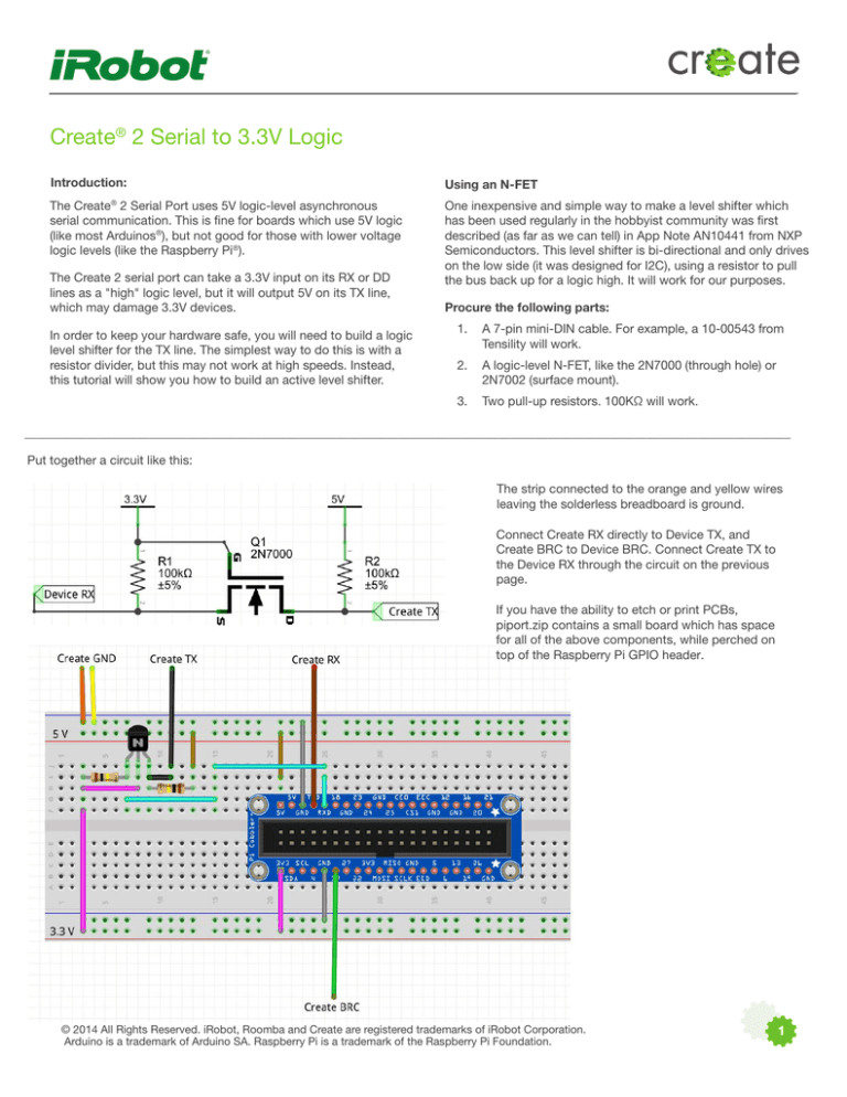
Put together a circuit like this:
The strip connected to the orange and yellow wires
leaving the solderless breadboard is ground.
Connect Create RX directly to Device TX, and
Create BRC to Device BRC. Connect Create TX to
the Device RX through the circuit on the previous
page.
If you have the ability to etch or print PCBs,
piport.zip contains a small board which has space
for all of the above components, while perched on
top of the Raspberry Pi GPIO header.
© 2014 All Rights Reserved. iRobot, Roomba and Create are registered trademarks of iRobot Corporation.
Arduino is a trademark of Arduino SA. Raspberry Pi is a trademark of the Raspberry Pi Foundation.
1
With a 5V-tolerant 3.3V buffer
A buffer will actively drive its output both high and low, which will
give faster edge times. We used one gate of a 74LVC245, which
is available at Adafruit. This tutorial is aimed at interfacing with
a Raspberry Pi.
Procure the following parts:
• Prototyping board
• 74LVC245 octal bus transceiver
• 0.1uF leaded ceramic capacitor
• 22 or 24 AWG hookup wire
• A 7-pin mini-DIN cable
• Optional: 4-40 x 5/8” or M3 x 16 mm standoff to support
prototyping board if installing above Raspberry Pi
If you are hooking up to a Raspberry Pi, we recommend the
following configuration. Colored wire shown leaving the board is
the same as the Tensility cable, which is as follows:
3
5
1
6
7
2
8
4
Front Side
1.
Wire the Adafruit prototyping board (http://goo. gl/Gni2xf)
as shown. Seven holes are marked with diamonds; these
correspond to the colors of the wires in the 7-pin mini-DIN
cables from Tensility.
2.
Cut the USB A to USB Micro B cable in half and put aside
the A side for later projects. Cut away the insulation and
shield. You may also cut the white and green wires, as they
are not used to power the Raspberry Pi. Connect the red
wire to the positive voltage output from the buck converter,
and the black wire to the zero voltage (ground reference).
3.
Install the 2 x 13 pin header provided with the Adafruit
prototyping plate into your Raspberry Pi, and then install
the prototyping plate on top of the header, as shown in
the Adafruit learning portal ( http://goo.gl/EeZGGx ), and
solder it in place.
4.
With a model A board, there is no place for the bumper in
the second step of the Adafruit tutorial to rest. In order to
support the prototyping board, we installed a 5/8” standoff
in the Raspberry Pi mounting hole closest to the HDMI
connector. A 16 mm standoff should work fine, too.
1. red wire
2. purple wire
3. black wire
4. brown wire
5. orange wire
6. yellow wire
7. green wire
8. drain wire
• Pins 1 and 2 are Roomba battery voltage. When the Create® 2
is plugged into the charger, this can be as high as 21V! Please
be sure your device can handle it before plugging these wires in.
• Pin 3 is Roomba TX, which will go to the FET’s drain.
• Pin 4 is Roomba RX, which goes into the device’s TX.
• Pins 5 and 6 are Ground.
• Pin 7 is Roomba BRC, which goes into a device GPIO.
For the Raspberry Pi, we recommend pin 17.
Note that the Tensility cable uses the opposite pin numbering
convention as Roomba.
© 2015 All Rights Reserved. iRobot, Roomba and Create are registered trademarks of iRobot Corporation.
Arduino is a trademark of Arduino SA. Raspberry Pi is a trademark of the Raspberry Pi Foundation.
2


