Sample Design Abstract Flux Qubit Experimental Setup Results
advertisement
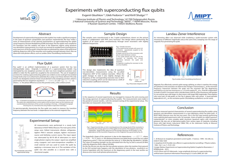
Experiments with superconducting flux qubits Evgenii Glushkov1,2, Gleb Fedorov1,2 and Kirill Shulga1,2,3 1 Moscow Institute of Physics and Technology, 141700 Dolgoprudnii, Russia 2 National University of Science and Technology "MISIS", 119049 Moscow, Russia 3 Russian Quantum Center, 143025 Skolkovo, Russia Abstract Sample Design Landau-Zener Interference Development of superconducting quantum bits (qubits) has made a significant progress in the areas of quantum computation and quantum metamaterials. We have made a series of measurements of the spectral characteristics of superconducting flux qubits using Frequency Division Multiplexing (FDM) technique. The flux qubits were coupled to λ/4 resonators and the readout was done in the dispersive regime using quantum non-demolition measurements. As a result we received an avoided-level crossing picture and a spectrum of the flux qubit. Using that data we obtained the values of the qubit level splitting, dispersive shift of the resonator and coupling strength between them. Also we observed multi-photon effects, such as Landau-Zener-Stuckelberg interferometry. The samples were manufactured in the 7-qubit architechture, shown on the picture below, in collaboration with IPHT, Jena, Germany3. This design allows performing the readout of all seven qubits simultaneously through seven resonators with slightly different frequencies. An interesting effect was observed while irradiating a qubit-resonator system with microwaves of different magnitudes and, at the same time, sweeping over the range of magnetic flux penetrating the qubit. Flux Qubit Flux qubit1 is an artificial implementation of a quantum system that has two distinguishable states. Originally it consisted of a superconducting metallic ring interrupted by one Josephson junction (JJ), later two more Josephson junctions were added to make the flux qubit less coupled to the environment. The use of Josephson junctions for creating superconducting qubits was evident as one could get two isolated energy levels only in an anharmonic potential, thus using a non-linear element. The only known non-dissipative and non-linear circuit element is the Josephson junction, which is (1) and (2), governed by the two Josephson equations2: where φ is the phase difference across the junction and I0 is the critical current. Fig. 2 Sample overview: a) The experimental sample with seven λ/4 resonators, capacitevely coupled to the common feedline. b) Upper end of one of the resonators with pins to catch Abrikosov vortices. c) Flux qubit placed near the end of the resonator to maximize the mutual inductance between the qubit and resonator. d) Capacitor coupling the resonator to the common feedline. This design also implements the idea of quantum non-demolition measurements using ths so-called “dispersive shift” of the readout resonator. When the qubit changes its state it also slightly changes the frequency of the corresponding resonator due to their inductive coupling, which can be observed as a shift of the transition coefficient minimum. Fig. 6 Landau-Zener-Stuckelberg Interference4 Fig. 3 Resonator dispersive shift. Results Fig. 1 a) Detailed micrograph of an aluminum flux qubit with 3 JJ. b) Schematic view of a 3JJ flux qubit, also called persistent-current qubit as the two basis states are the clockwise and counterclockwise directions of the current, circulating in the loop. c) Enlarged micrograph showing two JJ’s, manufactured using shadow evaporation technique. In the sequence of several experiments we managed to measure the anti-crossing and the energy spectrum of superconducting flux qubits. The measurements were made in the period of several months, with the constant tuning of the experimental setup . The best data we measured is shown below. Conclusion To spectroscopically characterize the flux qubit one needs to measure the transition frequency between the two levels in dependance to the external magnetic flux. We have measured spectral characteristics of several superconducting flux qubits using quantum non-demolition measurements in a new laboratory, which has been built in NUST MISIS, Moscow over the last two years. This is the fisrt step towards performing more sophisticated experiments with, for example, chains of qubits (so-called, “quantum metamaterials”) or more complex qubit structures (quantum optics with microwave photons). We also aim at fabricating qubits from various types of materials, including those with high kinetic inductance (NbN, TiN), at the cleanroom facility at Moscow Institute of Physics and Technology. Experimental Setup Fig. 4 Schematic view of the experimental setup. All measurements were performed in a newly built laboratory in NUST MISIS, Moscow. The main parts of the setup were Oxford Instruments dilution refrigerator, Agilent PNA-X network analyzer, Agilent microwave source and Keitheley current source. The input signal was attenuated by 60-70 dB of attenuators to reach single-photon regime, the output signal was amplified using cryogenic and room-temperature amplifiers. A small external coil was used to excite the qubit by applying a microwave tone to it. The excitation of the qubit was also possible as a second tone with a directional coupler. Magnetic flux effectively controls qubit energy splitting, so when it matches the energy of k photons in the resonator, we observe the change in transmission S21 at the resonator frequency. Interaction between the qubit and the resonator lifts the degeneracy, permitting us to see two resonances, ω r ± Ω, and a peak of S21 at ωr. That lift is dependent on both n and Φ: it increases with n and decreases with Φ, so the resonances with greater k’s can only be seen with larger n’s, that means, with larger MW magnitudes. That explains why every pair of side-peaks on the Fig. 6 appears later with power. A quasi-periodic dependence of S21 on the excitation power (Stuckelberg oscillations) can be noted. Fig. 5 Experimental data. a) Anti-crossing picture: the energy level of the resonator is crossed by the energy spectrum of the qubit at two points. This happens due to the hyperbolic shape of the spectrum. b) The energy spectrum of the qubit, i.e. the dependance of the transition frequency on the magnetic flux governed by Eq. (3). The hyperbolic shape of the spectrum is due to the dependance , where and and ∆ is the distance between two qubit levels at zero flux (so-called “degeneracy point”). One can estimate the value of ∆ from the Fig. 5b which is 1.8 GHz. The value of coupling strength can be estimated from the Fig. 5a and is around 20 MHz while the dispersive shift is about 0.8 MHz. On the Fig. 5b one can also see the two-photon process, when the trasition from ground to the first excited state happens with the absorbtion of two photons, resulting in an inverse hyperbola with the maximum at the degeneracy point. In the next section we disscuss one more multi-photon phenomenon. References 1. JE Mooij et al. Josephson persistent-current qubit. // Science. -1999. - Vol. 285, no. 5430-P. 1036-1039 2. Josephson B. D. Possible new effects in superconductive tunnelling // Physics Letters. -1962.- Vol. 1, no. 7. -P. 251-253 3.Jerger Markus. Experiments on Superconducting Qubits Coupled to Resonators. // KITBibliothek. - 2013. 4. W. D. Oliver and S.O. Valenzuela. Large-amplitude driving of a superconducting artificial atom. Quantum Information Processing 8, 2-3 (June 2009), 261-281
