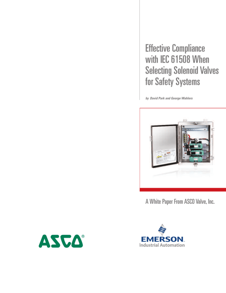
Effective Compliance
with IEC 61508 When
Selecting Solenoid Valves
for Safety Systems
by David Park and George Wahlers
A White Paper From ASCO Valve, Inc.
Introduction
Regulatory modifications in 2010 have raised important issues in design and use of industrial safety systems. Certain changes in IEC 61508, now being widely implemented, mean
that designers and users who desire full compliance must give new consideration to
topics such as SIL levels and the transition from 1H to 2H methodologies.
In particular, these issues can impact users’ selection of solenoid valves and prepackaged redundant control systems (RCS) for implementation in a safety instrumented
system (SIS). Such selections may also be affected by how experienced valve suppliers
are at dealing with complex new compliance methodologies.
These issues are especially applicable to the oil, gas, chemical, and power industries —
in applications such as safety shutdown systems, boilers, furnaces, high-integrity protection systems (HIPS), and more. They’re of concern to safety engineers and reliability
engineers, as well as to process engineers, engineering executives, and plant managers.
This report will address these issues in developing a compliant SIS using valves and
RCSs. Making the right choices in safety system planning and in valve supplier selection
can affect design time, costs, and effort — as well as the safety of the plant itself.
Safety in process
Every industrial plant must be concerned with risks to its safety, and to the mitigation of
those risks. Safety of process components continues to be of critical importance in light
of periodic industrial disasters such as Buncefield, Deepwater Horizon, and the
November 2013 oil pipeline explosion in Qingdao, China.
Such events naturally draw media attention, and often increase regulatory pressures on
all operations. In plants that actually suffer these or even lesser safety incidents, consequences can include the trouble and costs of process downtime — as well as the para-
2
mount considerations of harm to employees, the community, and the environment. Thus
planners at all industrial process operations must avoid complacency on safety issues.
Certified solenoid valves properly used in SISs are important elements of any corporate
risk mitigation strategy.
Evolving standards
IEC 61508, titled “Functional Safety of Electrical/Electronic/Programmable Electronic
Safety-Related Systems,” is the accepted international standard that guides selection of
components for industrial safety systems. Its latest revision, explained below, was issued
in 2010.
However, certain provisions of this standard — especially Route 2H, — are only now
becoming widely implemented. In fact, engineering groups at numerous process manufacturers are currently wrestling with complexities arising from these issues as they
evolve fresh approaches to adjust to the new standard.
Note that the technicalities may be daunting, as this report itself demonstrates. An
extensive selection of specialized concepts and terms are introduced here (plus their
accompanying initialisms, from SIS, SIL, and SIF to PFDavg, FMEDA, and FIT). All of
these are used in determining correct compliance. Their number and scope give some
indication of the difficulties facing professionals who may not be well versed in this
area of safety practice.
Thus many designers and safety engineers tackling these changes find it helpful to consult a knowledgeable solenoid valve supplier. They report that their supplier’s experts can
help deliver welcome savings in schedules and cost. This allows engineers to devote
more attention to other critical parts of the project.
Evaluating solenoid valve redundancy and SIL
The safety engineer faces numerous challenges in designing an efficient SIS for a given
plant process. He or she must decide what technology should be selected, what level of
risk reduction must be achieved, what architecture is appropriate for the given control
system components, and what testing is required to reach the system’s desired safety
integrity level (SIL). System development includes how frequently diagnostic test are
performed both manually and automatically and is important because frequent testing
may mean system downtime.
3
In particular, when selecting crucial technology such as solenoid valves, the engineer
must begin by considering three factors:
1. Architectural constraints dictate the required level of redundancy needed to achieve a
desired SIL level for a given safety instrumented function (SIF). This redundancy is
referred to as the hardware fault tolerance (HFT).
2. A solenoid valve’s average probability of failure on demand (PFDavg) determines the
device’s contribution to the SIF’s overall PFDavg when used with other devices, not its
SIL-capability as a stand-alone device.
3. Does the device possess IEC 61508 certification? Certification indicates that its manufacturer’s design, manufacturing, and quality procedures satisfy this IEC standard’s
requirements for the device’s listed SIL capability.
Once the SIF is designed, SIL verification calculations determine if it will provide the
desired risk reduction. For example, the safety engineer may use the following simplified
formula on a single-channel, one out of one (1oo1) SIF with proof test coverage to determine if the PFDavg meets the desired SIL level:
PFDAVG–1oo1 =
(1 – CPT * λDU * LT
CPT * λDU * TI
+ (λDD * MTTR) +
2
2
PFDAVG–1oo1
= Average Probability of Failure on Demand
DU
= Dangerous Undetected failure rate
DD
λ
= Dangerous Detected failure rate
TI
= Proof Test Interval
MTTR
= Mean Time To Restore
CPT
= Manual Proof Test Coverage = λDD / (λDD + λDU)
LT
= Lifetime of the system
λ
Consideration of certification is the next step. Devices such as solenoid valves are categorized as type A devices — “non-complex” mechanisms that possess discrete elements
according to IEC 61508 (2010).
Certification begins with a failure mode effect and diagnostics analysis (FMEDA). This
analysis determines the failures in time (FIT) rates “λ” for different types of failures: safe
detected, safe undetected, dangerous detected, and dangerous undetected. Once these
rates are established, the safe failure fraction (SFF) and PFDavg can be calculated:
4
SFF =
λSD + λSU + λDD
λSD + λSU + λDD + λDU
Failure rate types
λSD = Safe Detected failure rate
λSU = Safe Undetected failure rate
λDD = Dangerous Detected failure rate
λDU = Dangerous Undetected failure rate
IEC 61508 allows two routes to determine a solenoid valve’s SIL capability. The traditional
Route 1H uses FIT rates to calculate a safe failure fraction (SFF) for the given valve. The
SFF can then be used to determine the HFT, which in turn can establish the level of
redundancies required in using this valve, and can show what SIL level the safety function utilizing this valve would attain.
As part of an effort to reduce ambiguity in failure type definitions, for its 2010 release IEC
61508 altered the SFF formula used in Route 1H. Briefly, “no effect” failures are no longer
a component of safe failures.
This change usually produces a lower SFF in the formula above. If the SFF values drop
below certain thresholds as shown in the table below, a higher HFT than before is
required to achieve desired SIL levels. For example, a valve with an SFF of 75% would be
SIL 3 capable with an HFT of 1. But if the SFF dropped below 60%, the valve would only
be SIL 2 capable with that same HFT of 1.
Type A Subsystem
Safe Failure
Fraction (SFF)
Hardware Fault Tolerance (HFT)
0
1
2
< 60%
SIL 1
SIL 2
SIL 3
60% to < 90%
SIL 2
SIL 3
SIL 4
90% to < 90%
SIL 3
SIL 4
SIL 4
≥ 99%
SIL 3
SIL 4
SIL 4
Note: An HFT of N means that N+1 faults could
cause a loss of the safety function.
5
Evaluating Routes 1H and 2H
Another major change in the 2010 release of IEC 61508 was the introduction of Route 2H.
This began the process whereby some certifying agencies are phasing out Route 1H
approaches for evaluation of final elements (solenoid valves, actuators, ball valves, etc.).
As with Route 1H, failure rates (λ) are first determined via lab testing or FMEDA calculation. But instead of SFF and HFT, Route 2H uses the failure rates to determine PFDavg and
HFT for SIL capability.
And perhaps most importantly, Route 2H affirms the failure rates with historical information — actual customer field return data on component reliability. In fact, Route 2H can
only be applied if there is sufficient field data to support the failure rates used in the
PFDavg calculations and that a valve is proven in use. If so, this data can be used to
determine SIL levels.
How is that historical data obtained? It’s most often available when dealing with a supplier
who has received validation from leading independent global safety certification sources,
such as Exida or TÜV. Failure rates for numerous ASCO parts and components are supported by data collected by Exida arising from literally billions of hours of operation.
The paramount advantage of using Route 2H: its higher confidence level. This refers to
the statistical probability that the actual failure rate — λactual — will fall between the
limits λ5% and λ95% (which are at the higher and lower edges of a bell curve, respectively). While Route 1H usually exhibits only 70% confidence, Route 2H typically achieves
90% — promising a 90% certainty that the predicted failures will occur as expected. This
higher confidence is possible due to the support of calculated failure rates by actual field
return data, and the ability to take more uncertainties into account.
Note that Route 1H will still be used for electronic or other complex devices, programmable systems, and other devices incorporating diagnostics. Route 2H is applied to
simple or mechanical products such as valves and other final elements.
Nevertheless, industry-wide acceptance of the Route 2H method has been growing
steadily since it was first implemented. Agencies such as exida use the Route 2H
approach for both new and renewed certifications. Some customers have been understandably hesitant to adopt it because of existing investments in their systems using
Route 1H. Fortunately, changing from the 1H to the 2H approach makes little or no difference in certification. We recommend that users become familiar with Route 2H and
understand its significance.
6
Evaluating suppliers
For the safest system design, selecting the right solenoid valve supplier may be as important as any of the technical choices discussed above.
Solenoid valves are too critical to be purchased as mere commodities; avoid vendors
who emphasize the lowest price alone. Look instead for a supplier that’s deeply involved
in safety issues, understands what’s involved in setting up a safety system, and has comprehensive resources to provide technical support.
Safety certification of valve components can involve considerable complexities for the
supplier. Gravitate toward suppliers who have taken the trouble to obtain such certification — and who are validated by independent sources. ASCO possesses the world’s
widest variety of SIL-certified pilot valve solutions. Many of these products have certifications from both Exida and TÜV international agencies.
Ask the right questions. When you’re evaluating products for an SIS, does a given supplier furnish your required level of local/international service/support? Does it provide a
comprehensive selection, so you can find precisely the products you need?
Conclusion
Safety is a critical requirement for most if not all industrial plants. It’s vital that users keep
up with new developments in regulation and technology within this fast-changing field.
This is particularly true of the ability to make informed decisions on issues such as compliance with IEC 61508, consideration of SIL levels, transition from 1H to 2H, and selecting
solenoid valves.
An experienced solenoid valve supplier that’s knowledgeable about these issues can
serve as a valuable resource for advice and information. Users who stay informed can
ensure compliance and improve savings and process safety.
Takeaways
• IEC 61508 has new methods to determine SIL-capability for valves used
in safety systems.
• Designers and users must consider valve redundancy, SIL levels, and
transition from 1H to 2H certification methodologies
• A valve supplier concerned with and experienced in compliance topics
can remove much of the burden of these issues in safety system design
• Making correct choices can affect design time, costs, and effort, as
well as overall plant safety
7
Global Contacts
www.ascovalve.com
ASCO Headquarters (U.S.A.)
Tel: 800-972-ASCO (2726) or
+1 973-966-2000
info-valve@asco.com
Global Headquarters
Regional Headquarters
Manufacturing & Key Offices
Other Worldwide Locations
Australia
(61) 2-9-451-7077
Italy
(39) 02-356931
Brazil
(55) 11-4208-1700
Japan
(81) 798-65-6361
Canada
(1) 519-758-2700
Mexico
(52) 55-5809-5640
China
(86) 21-3395-0000
Netherlands
(31) 33-277-7911
Czech Republic
(420) 235-090-061
Singapore
(65) 6556-1100
Dubai - UAE
(971) 4-811-8200
South Korea
(82) 2-3483-1570
France
(33) 1-47-14-32-00
Spain
(34) 942-87-6100
Germany
(49) 7237-9960
Turkey
(90) 216-577-3107
India
(91) 44-39197300
United Kingdom
(44) 1695-713600
4
The ASCO logo is a trademark of Automatic Switch Co.
The Emerson logo is a trademark and service mark of Emerson Electric Co.
All other trademarks are the properties of their respective owners.
© 2014 ASCO Valve, Inc. All rights reserved.
Printed in the U.S.A.
1331036


