What is Power Factor
advertisement
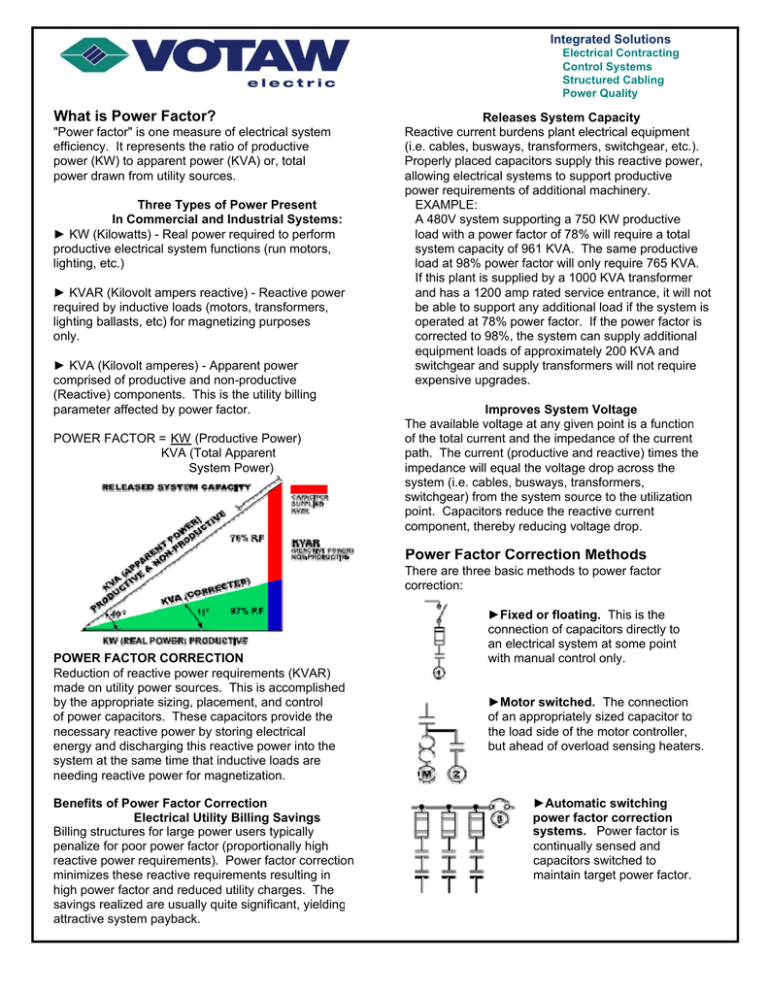
Integrated Solutions Electrical Contracting Control Systems Structured Cabling Power Quality What is Power Factor? "Power factor" is one measure of electrical system efficiency. It represents the ratio of productive power (KW) to apparent power (KVA) or, total power drawn from utility sources. Three Types of Power Present In Commercial and Industrial Systems: ► KW (Kilowatts) - Real power required to perform productive electrical system functions (run motors, lighting, etc.) ► KVAR (Kilovolt ampers reactive) - Reactive power required by inductive loads (motors, transformers, lighting ballasts, etc) for magnetizing purposes only. ► KVA (Kilovolt amperes) - Apparent power comprised of productive and non-productive (Reactive) components. This is the utility billing parameter affected by power factor. POWER FACTOR = KW (Productive Power) KVA (Total Apparent System Power) Releases System Capacity Reactive current burdens plant electrical equipment (i.e. cables, busways, transformers, switchgear, etc.). Properly placed capacitors supply this reactive power, allowing electrical systems to support productive power requirements of additional machinery. EXAMPLE: A 480V system supporting a 750 KW productive load with a power factor of 78% will require a total system capacity of 961 KVA. The same productive load at 98% power factor will only require 765 KVA. If this plant is supplied by a 1000 KVA transformer and has a 1200 amp rated service entrance, it will not be able to support any additional load if the system is operated at 78% power factor. If the power factor is corrected to 98%, the system can supply additional equipment loads of approximately 200 KVA and switchgear and supply transformers will not require expensive upgrades. Improves System Voltage The available voltage at any given point is a function of the total current and the impedance of the current path. The current (productive and reactive) times the impedance will equal the voltage drop across the system (i.e. cables, busways, transformers, switchgear) from the system source to the utilization point. Capacitors reduce the reactive current component, thereby reducing voltage drop. Power Factor Correction Methods There are three basic methods to power factor correction: POWER FACTOR CORRECTION Reduction of reactive power requirements (KVAR) made on utility power sources. This is accomplished by the appropriate sizing, placement, and control of power capacitors. These capacitors provide the necessary reactive power by storing electrical energy and discharging this reactive power into the system at the same time that inductive loads are needing reactive power for magnetization. Benefits of Power Factor Correction Electrical Utility Billing Savings Billing structures for large power users typically penalize for poor power factor (proportionally high reactive power requirements). Power factor correction minimizes these reactive requirements resulting in high power factor and reduced utility charges. The savings realized are usually quite significant, yielding attractive system payback. ►Fixed or floating. This is the connection of capacitors directly to an electrical system at some point with manual control only. ►Motor switched. The connection of an appropriately sized capacitor to the load side of the motor controller, but ahead of overload sensing heaters. ►Automatic switching power factor correction systems. Power factor is continually sensed and capacitors switched to maintain target power factor.
