®
®
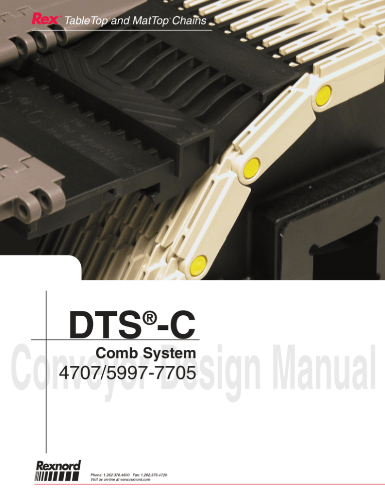
DTS -C
®
Conveyor Design Manual
Comb System
4707/5997-7705
Rexnord, Rex, TableTop, MatTop and DTS-C are trademarks of Rexnord Industries, Inc.
All rights reserved.
®
®
Table of Contents
Introduction / Safety . . . . . . . . . . . . . . . . . . . . . . . . . . . . . . . . . 2-3
Components . . . . . . . . . . . . . . . . . . . . . . . . . . . . . . . . . . . . . . . . 4-5
Basic Design Considerations . . . . . . . . . . . . . . . . . . . . . . . . . . . . . 6
Installation . . . . . . . . . . . . . . . . . . . . . . . . . . . . . . . . . . . . . . . . 7-10
· Comb mounting
·
Wearstrip Mounting
Appendix / Drawings . . . . . . . . . . . . . . . . . . . . . . . . . . . . . . . . 11-15
Rex® DTS®-C Design Manual
(v1.2)
DM-DTS-C-1
®
®
Introduction
As products are becoming less stable, conveyor applications are becoming more
demanding. Pasteurizers, coolers, warmers, and accumulation tables utilize either raised rib
chains with transfer combs or perforated top chains with DTS® transfers. With raised rib
chains, the benefit of the transfer combs is a smooth transfer. The primary benefit of a
DTS® system is self clearing transfers for continuous product flow.
The DTS®-C System combines the best of both worlds with an ultra smooth transfer as well
as continuous and self clearing product flow.
In addition the DTS®-C provides better stiffness at the transfer as well as improved fingertip
support. The unique and patented feature of the DTS®-C System is the continuous flow of
product to and from a raised rib chain. The finger transfer is combined with a DTS® chain
so that products do not accumulate at pasteurizer, warmer, cooler or accumulation table
infeed & discharge areas.
With improved stiffness compared to standard transfer plates, the infeed and discharge
DTS® chains are fully supported so product tipping is avoided.
This manual shows the proper design and installation recommendations for the DTS®-C
transfer system. Chain dimensions and basic conveyor design considerations are
included. Following the suggestions outlined will ensure proper operation of the conveyor
and will provide the longest possible chain life.
The DTS®-C system is designed for cans, glass bottles and PET bottles. For optimum
performance of the DTS®-C transfer system, it is recommended to follow these
guidelines carefully.
Rex® DTS®-C Design Manual (v1.2)
DM-DTS-C-2
®
®
Safety Considerations
PRODUCT SAFETY: Products designed and manufactured by Rexnord are capable of
being used in a safe manner; but Rexnord cannot warrant their safety under all
circumstances. PURCHASER MUST INSTALL AND USE THE PRODUCTS IN SAFE
AND LAWFUL MANNER IN COMPLIANCE WITH APPLICABLE HEALTH AND SAFETY
REGULATIONS AND LAWS AND GENERAL STANDARDS OF REASONABLE CARE;
AND IF PURCHASER FAILS TO DO SO, PURCHASER SHALL INDEMNIFY REXNORD
FROM ANY LOSS, COST OR EXPENSE RESULTING DIRECTLY OR INDIRECTLY
FROM SUCH FAILURE.
SAFETY DEVICES: Products are provided with only safety devices identified herein. IT IS
THE RESPONSIBILITY OF PURCHASER TO FURNISH APPROPRIATE GUARDS FOR
MACHINERY PARTS in compliance with MSHA or OSHA Standards, as well as any other
safety devices desired by Purchaser and/or required by law; and IF PURCHASER FAILS
TO DO SO, PURCHASER SHALL INDEMNIFY REXNORD FROM ANY LOSS, COST OR
EXPENSE RESULTING DIRECTLY OR INDIRECTLY FROM SUCH FAILURE.
Rex® DTS®-C Design Manual (v1.2)
DM-DTS-C-3
®
®
Components
To utilize the DTS® -C 4707/5997-7705 product the following components are required:
1) 5997 or 4707
MatTop® Chain
2) 7705DTS® -450 Chain With
Positrack™ Tracking Guides
Any 0.50 in thick
Rex®TableTop® and
MatTop® chain
(7705,1055 chain)
4) DTS® -C Transfer Comb
3) Wearstrip
Number 5 not shown
1)
DIRECTION
OF TRAVEL
(
DIRECTION
OF TRAVEL
Chain Height
to Top of Ribs
0.97 in
(24.6 mm)
Chain Height
0.50 in
(12.7 mm)
Min. Back-flex Radius
2.75 in
(69.9 mm)
Chain Pitch
1.50 in
(38.1 mm)
Rex® 4707 MatTop® Chain Drawing
Rex® DTS®-C Design Manual (v1.2)
Chain Bottom
to Centerline
0.36 in
(9.1 mm)
Chain Bottom
to Centerline
0.25 in
(6.4 mm)
Chain Height
to Top of Ribs
0.75 in
(19.1 mm)
Min. Back-flex Radius
2.00 in
(50.8 mm)
Direction of Travel for
) Preferred
glass and bottle handling
Chain Width
DIRECTION
OF TRAVEL
Chain Width
1)
Chain Height
0.72 in
(18.2 mm)
Chain Pitch
2.25 in
(57.2 mm)
OR
Rex® 5997 MatTop® Chain Drawing
DM-DTS-C-4
®
®
Components
DIRECTION
OF TRAVEL
0.18 in
(4.16 mm)
Guide Clearance
1.75 in
(44.5 mm)
Tracking Guide Spacing
1.70 in
(43.2 mm)
Blade Length
2.04 in
(51.7 mm)
3)
6.30 in (160.0 mm) Chain Width
2)
Wearstrip
Dimensions
2.26 in
(57.2 mm)
0.20 in
(5.1 mm)
Note: Supplied in 10 ft (3.048 m) sections
Chain Pitch
1.00 in
(25.4 mm)
Left-hand
Transfer
Wearstrip Drawing
1.40 in
(35.6 mm)
Chain Bottom
to Centerline
0.25 in
(6.4 mm)
Min. Back-flex Radius
1.00 in
(25.4 mm)
Chain Height
0.50 in
(12.7 mm)
Top of Chain to
Bottom of
Tracking Guide
0.90 in
(22.9 mm)
5)
Right-hand
Transfer
7705DTS® Part Numbers
Part Number
Left Hand
Right Hand
7705-4.5 DTS® W/PT
814-13921
814-13931
Description
¼ in
Rex® 7705DTS® -450 MatTop® Chain with
Positrack™Tracking Guides Drawing
Note: This plate is not supplied by Rexnord
Steel Mounting Plate
4)
3)
5)
Wearstrip
114-4160-1
DTS®-C Transfer Plate
4) 114-4151-1
Steel Mounting
Plate
(Not Supplied
By Rexnord)
1)
Cap Screws
114-870-1 (¼-20 Thread)
Comb Drawing
Rex® Transfer Comb Kit
DTS®-C Component Part Numbers
Component
Description
DTS®-C
Comb Kit
Wearstrip
Wearstrip
Kit
Comb
Screw
Part Number
Part Number Part Number Part Number
(10ft length)
614-448-1
114-4151-1
114-870-1
NA
NA
114-4160-1
For Use With:
Raised Rib
Chain
DTS® Chain
Takeaway Chain
5997 or 4707
7705DTS-450
7705, 7706,
or 1055
Wearstrip is sold in 10 ft (3.048 m) lengths and is sold separately
Rex® DTS®-C Design Manual (v1.2)
DM-DTS-C-5
®
®
Basic Design Considerations
The DTS®-C should be installed according to assembly drawing as shown in Figure 1.
·
Dimension “G” is a nominal dimension and may have to be adjusted for "fine tuning" for
each specific application
Center of Sprocket to Edge of 7705-4.50 DTS® Chain
7.95 in
(202.1 mm)
"B" Dimension
1.32 in
(36.6 mm)
1.65 in
(42.0 mm)
0.25 in
(6.4 mm)
0.39 in
(10.0 mm)
¼-20 Thread
Transfer Plate
Mounting Screw
"A" Dimension
"G" Dimension
"D" Dimension
"C" Dimension
2.51 in
(63.5 mm)
ket
proc
Pitch
eter
Diam
S
Figure 1. DTS®-C 4707/5997 - 7705DTS Shaft Drop Drawing
®
DTS -C Shaft Drop Dimensions
Sprocket
Chain
Num ber
4707
5997
No of
Eff. No
Teeth
of Teeth inches
Dim ensions
Pitch Diameter
"A" Dimension
mm
inches
mm
"B" Dimension
"C" Dimension
inches
inches
mm
mm
"D" Dimension
"G" Dimension
inches
mm
inches
mm
2.98
75.7
1.41
35.7
3.22
81.7
1.64
41.7
3.45
87.7
1.88
47.7
21
10½
5.08
129.0
2.30
58.3
23
11½
5.56
141.2
2.53
64.3
25
12½
6.03
153.2
2.77
70.3
27
13½
6.5
165.1
3.00
76.3
3.69
93.6
2.11
53.7
9
9
6.57
166.9
2.93
74.4
3.84
97.5
2.26
57.5
12
12
8.69
220.7
3.99
101.3
4.90
124.3
3.32
84.3
14
14
10.11
256.8
4.69
119.1
5.60
142.3
4.03
102.3
7.717
7.717
196.0
196.0
1.50
2.25
38.1
57.2
Table 1. Shaft Drop Dimensional Values for DTS®-C 4707/5997-7705
Rex® DTS®-C Design Manual (v1.2)
DM-DTS-C-6
®
®
Installation
Comb Mounting
!
CAUTION
·
·
·
All DTS®-C modules should be mounted level
The steel mounting plate should be level and straight
The straightness and flatness of the plate will have a large effect on overall system
performance
·
The DTS®-C must be able to float axially to allow for thermal expansion and contraction of the
chain (see Figure 3)
·
·
The shouldered screws supplied with the kit must be used to mount the combs
The DTS®-C combs should be positioned so that the teeth ride on the chain between the ribs.
In other words, the bottom of the teeth should contact the bottom of the valley between the
ribs of the 4707 or 5997 chain. Refer to Figures 4 and 5
·
The DTS®-C combs are equipped with oblong holes, which are centered at 3 in (76.2 mm) pitch.
These oblong holes are used to bolt the combs onto the supporting profile.The supporting profile
must be drilled and tapped with ¼-20 holes at 3 in (76.2 mm) pitch. Using 3 in (76.2 mm) pitch
enables the comb to accommodate thermal expansion over the full width of the machine
Center to Center
of Slots
3.00 in
(76.2 mm)
Figure 2. Mounting Slot Dimensions
Wearstrip Mounting
!
CAUTION
It is recommended that the wearstrip is secured (screwed, pinned, etc) near the tail shaft of the
DTS® conveyor, this allows the wearstrip to expand and contract in length to avoid wearstrip
buckling.
Rex® DTS®-C Design Manual (v1.2)
DM-DTS-C-7
®
®
Installation - Comb Mounting -Thermal Expansion & Contraction
The transfer comb mounting recommendations shown in the Rex Engineering Manual
(page EM-MT-50) also apply to the DTS®-C combs.
MatTop®
Conveyor
Design
CONVEYOR DESIGN RECOMMENDATIONS
Transfer Comb Installation
Low Temperature Application
> Transfer
Comb
Installation
Chain CL
Chain CL
> Low
Temperature
Application
Step 1
Step 1
Step 2
Step 2
> High
Temperature
Application
> Room
Temperature
Application
Allows for chain contraction.
> Combs
STEP 1 Secure the two center most transfer plates in order to track the chain
STEP 2 Position the fasteners in the remaining transfer plates to the corresponding right side or left
side of the slots to allow for contraction at low temperatures
High Temperature Application
Chain CL
Chain CL
Step 1
Step 1
Step 2
Step 2
Allows for chain expansion.
STEP 1 Secure the two center most transfer plates in order to track the chain
Rexnord, Rex, MatTop,
TableTop, HP, PS,
Platinum Series, UHS,
DTS, PosiClean, RexFlex,
Positrack, TwistLock and
DynamicTransfer
System are registered
trademarks of Rexnord
Industries, Inc.
Nylontron is a
registered trademark of
Quadrant Engineering
Plastics Products
All rights Reserved.
STEP 2 Position the fasteners in the remaining transfer plates to the corresponding right side or left
side of the slots to allow for expansion at high temperatures
i
This arrangement will allow these transfer plates to move as required to accommodate changes
in the chain width up to 1.50 in (38.1 mm).
Room Temperature Applications
STEP 1 Secure the two center most transfer plates in order to track the chain
STEP 2 The transfer plates to the left and right should have fasteners centered in the mounting slots
Combs
A variety of styles and materials are available
Chain CL
Step 1
Step 1
Step 2
Rex® MatTop® Chains
Step 2
Figure 3. Page EM - MT - 50 from Rex MatTop® Engineering Manual
Rex® DTS®-C Design Manual (v1.2)
DM-DTS-C-8
®
®
Installation - Final Adjustments Comb Adjustment for Optimum Performance
DTS-C Comb Level
with Top of
4707/5997 Chain
Longer Deadplate
Figure 4. A higher position of the DTS®-C transfer comb increases the dead plate length,
but will also provide a smooth product flow.
DTS-C Comb Level
with Top of
4707/5997 Chain
Shorter Deadplate
Figure 5. A lower position of the DTS®-C transfer comb decreases the dead plate length,
but will also decrease the product flow stability due to the chordal action of the raised rib chain.
!
CAUTION
· As a general rule of thumb, products with a footprint of greater than 4.2 in (106 mm) will
result in a self clearing DTS®-C system
· Optimum performance of the DTS -C is achieved by fine-tuning when running
®
the machine with the actual products
Rex® DTS®-C Design Manual (v1.2)
DM-DTS-C-9
®
®
Installation - Discharge Area Chain / Shaft / Gearbox Interference
!
CAUTION
The placement of the DTS®-C chain is critical. Be sure that the DTS® chain does not
interfere with the gearbox that drives the raised rib chain.
A few possibilities are as follows:
1) Guide the DTS® chain over the raised rib gearbox and place the DTS® gearbox after
the raised rib gearbox. For this design a compact gearbox is required for the raised
rib chain.
2) Guide the DTS® chain between the machine and the raised rib gearbox. For this design
a maximum shaft of 3 in or 80 mm must be utilized.
3) For 3-1/4 in or 90 mm shafts “B dimension” must be increased to 7.914 in (201.0 mm).
This will allow proper clearance between DTS® blade and shaft.
!
CAUTION
It is not recommended to use the DTS-C® system at the discharge end in high glass
breakage areas.
Rex® DTS®-C Design Manual (v1.2)
DM-DTS-C-10
®
®
APPENDIX
Rex® DTS®-C Design Manual (v1.2)
DM-DTS-C-11
®
®
DTS®-C Shaft Drop Drawing for 4707 Chain Operating On 21 Tooth Sprockets
DTS®-C Shaft Drop Drawing for 4707 Chain Operating On 23 Tooth Sprockets
Rex® DTS®-C Design Manual (v1.2)
DM-DTS-C-12
®
®
DTS®-C Shaft Drop Drawing for 4707 Chain Operating On 25 Tooth Sprockets
DTS®-C Shaft Drop Drawing for 4707 Chain Operating On 27 Tooth Sprockets
Rex® DTS®-C Design Manual (v1.2)
DM-DTS-C-13
®
®
DTS®-C Shaft Drop Drawing for 5997 Chain Operating On 9 Tooth Sprockets
DTS®-C Shaft Drop Drawing for 5997 Chain Operating On 12 Tooth Sprockets
Rex® DTS®-C Design Manual (v1.2)
DM-DTS-C-14
®
®
DTS®-C Shaft Drop Drawing for 5997 Chain Operating On 14 Tooth Sprockets
Rex® DTS®-C Design Manual (v1.2)
DM-DTS-C-15
www.rexnord.com
World Class Customer Service
For over 100 years the dedicated people of Rexnord have delivered
excellence in quality and service to our customers around the globe.
Rexnord is a trusted name when it comes to providing skillfully engineered products that improve productivity and efficiency for industrial
applications worldwide. We are committed to exceeding customer
expectations in every area of our business: product design, application engineering, operations and customer service.
Because of our customer focus, we are able to more thoroughly
understand the needs of your business and have the resources available to work closely with you to reduce maintenance costs, eliminate
redundant inventories and prevent equipment down time.
Rexnord represents the most comprehensive portfolio of power transmission and conveying components in the world with the brands you
know and trust.
The
Power of
Rexnord ™
FLATTOP
BEARINGS
GEARED
PRODUCTS
INDUSTRIAL
CHAIN
COUPLINGS
AEROSPACE
SPECIAL
COMPONENTS
WORLDWIDE CUSTOMER SERVICE
AUSTRALIA
Rexnord Australia Pty. Ltd.
Picton, New South Wales
Phone: 61.2.4677.3811
Fax: 61.2.4677.3812
CANADA
Rexnord Canada Ltd.
Scarborough, Ontario
Phone: 1.416.297.6868
Fax: 1.416.297.6873
EUROPE
Rexnord NV/SA
Mechelen, Belgium
Phone: 32.70.22.33.66
Fax: 32.70.22.33.67
LATIN AMERICA
Rexnord International, Inc.
Milwaukee, Wisconsin
Phone: 1.414.643.3000
Fax: 1.414.643.3222
UNITED STATES
Eastern Service Center
Atlanta, Georgia
Phone: 1.770.431.7200
Fax: 1.770.431.7299
BRAZIL
Rexnord Correntes Ltda.
Sao Leopoldo - RS
Phone: 55.51.579.8022
Fax: 55.51.579.8029
CHINA
Rexnord China
Shanghai, China
Phone: 86.21.62701942
Fax: 86.21.62701943
Rexnord Marbett, S.r.L.
Correggio (RE), Italy
Phone: 39.0522.639333
Fax: 39.0522.637778
MEXICO
Rexnord S.A. de C.V.
Queretaro, Qro.
Phone: 52.442.218.5000
Fax: 52.442.218.1090
Central Service Center
Grove City, Ohio
Phone: 1.614.675.1800
Fax: 1.614.675.1898
Rexnord FlatTop Europe b.v.
s-Gravenzande, Netherlands
Phone: 31.174.445111
Fax: 31.174.445222
8rxDTS-Cdm-en (v1.2)
SINGAPORE
Rexnord International, Inc.
Singapore City, Singapore
Phone: 65.6338.5622
Fax: 65.6338.5422
© Copyright 2005 Rexnord Industries, Inc.
Southern Service Center
Arlington, Texas
Phone: 1.817.385.2800
Fax: 1.817.385.2873
10/05


