Catalogue Sheet
advertisement
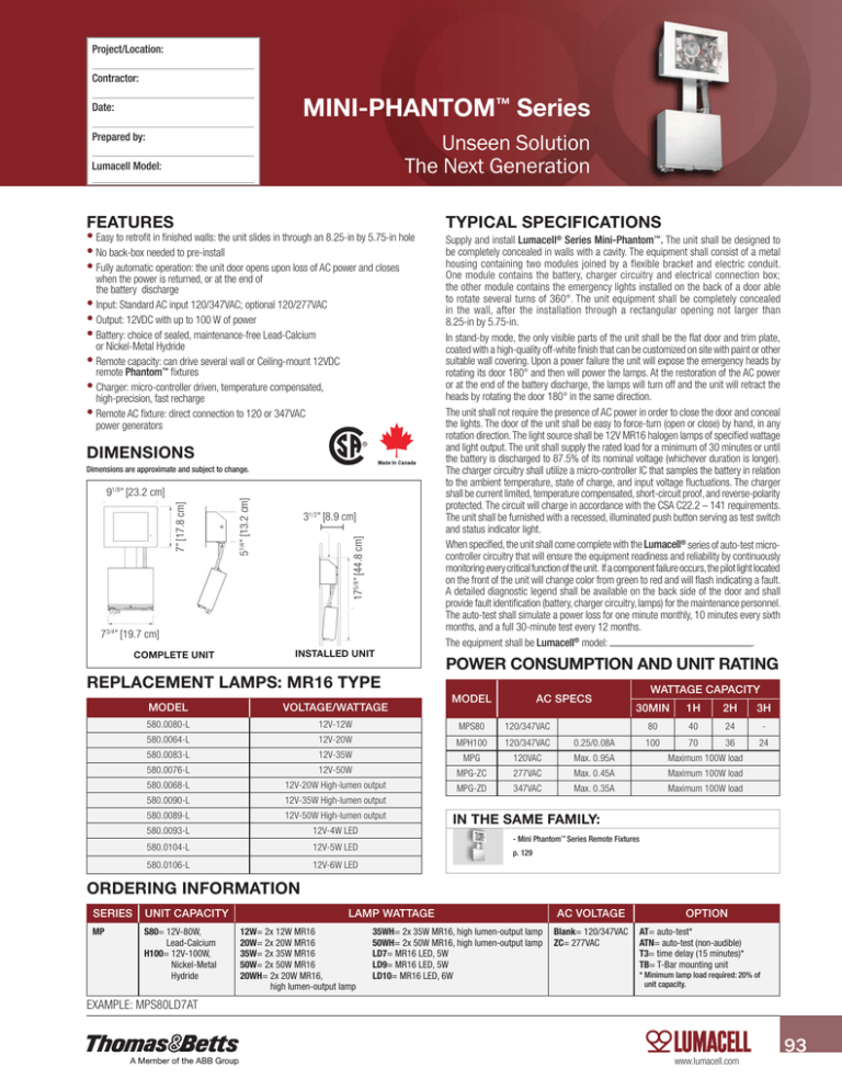
Project/Location: Contractor: MINI-PHANTOM™ Series Date: Unseen Solution The Next Generation Prepared by: Lumacell Model: FEATURES •Easy to retrofit in finished walls: the unit slides in through an 8.25-in by 5.75-in hole •No back-box needed to pre-install •Fully automatic operation: the unit door opens upon loss of AC power and closes when the power is returned, or at the end of the battery discharge •Input: Standard AC input 120/347VAC; optional 120/277VAC •Output: 12VDC with up to 100 W of power •Battery: choice of sealed, maintenance-free Lead-Calcium or Nickel-Metal Hydride •Remote capacity: can drive several wall or Ceiling-mount 12VDC remote Phantom™ fixtures •Charger: micro-controller driven, temperature compensated, high-precision, fast recharge •Remote AC fixture: direct connection to 120 or 347VAC power generators DIMENSIONS 31/2” [8.9 cm] 175/8” [44.8 cm] 7” [17.8 cm] 91/8” [23.2 cm] 51/4” [13.2 cm] Dimensions are approximate and subject to change. 73/4” [19.7 cm] COMPLETE UNIT INSTALLED UNIT REPLACEMENT LAMPS: MR16 TYPE TYPICAL SPECIFICATIONS Supply and install Lumacell® Series Mini-Phantom™. The unit shall be designed to be completely concealed in walls with a cavity. The equipment shall consist of a metal housing containing two modules joined by a flexible bracket and electric conduit. One module contains the battery, charger circuitry and electrical connection box; the other module contains the emergency lights installed on the back of a door able to rotate several turns of 360°. The unit equipment shall be completely concealed in the wall, after the installation through a rectangular opening not larger than 8.25-in by 5.75-in. In stand-by mode, the only visible parts of the unit shall be the flat door and trim plate, coated with a high-quality off-white finish that can be customized on site with paint or other suitable wall covering. Upon a power failure the unit will expose the emergency heads by rotating its door 180° and then will power the lamps. At the restoration of the AC power or at the end of the battery discharge, the lamps will turn off and the unit will retract the heads by rotating the door 180° in the same direction. The unit shall not require the presence of AC power in order to close the door and conceal the lights. The door of the unit shall be easy to force-turn (open or close) by hand, in any rotation direction. The light source shall be 12V MR16 halogen lamps of specified wattage and light output. The unit shall supply the rated load for a minimum of 30 minutes or until the battery is discharged to 87.5% of its nominal voltage (whichever duration is longer). The charger circuitry shall utilize a micro-controller IC that samples the battery in relation to the ambient temperature, state of charge, and input voltage fluctuations. The charger shall be current limited, temperature compensated, short-circuit proof, and reverse-polarity protected. The circuit will charge in accordance with the CSA C22.2 – 141 requirements. The unit shall be furnished with a recessed, illuminated push button serving as test switch and status indicator light. When specified, the unit shall come complete with the Lumacell® series of auto-test microcontroller circuitry that will ensure the equipment readiness and reliability by continuously monitoring every critical function of the unit. If a component failure occurs, the pilot light located on the front of the unit will change color from green to red and will flash indicating a fault. A detailed diagnostic legend shall be available on the back side of the door and shall provide fault identification (battery, charger circuitry, lamps) for the maintenance personnel. The auto-test shall simulate a power loss for one minute monthly, 10 minutes every sixth months, and a full 30-minute test every 12 months. The equipment shall be Lumacell® model: . POWER CONSUMPTION AND UNIT RATING MODEL AC SPECS WATTAGE CAPACITY MODEL VOLTAGE/WATTAGE 580.0080-L 12V-12W MPS80 120/347VAC 580.0064-L 12V-20W MPH100 120/347VAC 0.25/0.08A 580.0083-L 12V-35W MPG 120VAC Max. 0.95A Maximum 100W load 580.0076-L 12V-50W MPG-ZC 277VAC Max. 0.45A Maximum 100W load 580.0068-L 12V-20W High-lumen output MPG-ZD 347VAC Max. 0.35A Maximum 100W load 580.0090-L 12V-35W High-lumen output 580.0089-L 12V-50W High-lumen output 580.0093-L 12V-4W LED 580.0104-L 12V-5W LED 580.0106-L 12V-6W LED 30MIN 1H 2H 80 40 24 3H - 100 70 36 24 IN THE SAME FAMILY: - Mini Phantom™ Series Remote Fixtures p. 129 ORDERING INFORMATION SERIES UNIT CAPACITY MP S80= 1 2V-80W, Lead-Calcium H100= 12V-100W, Nickel-Metal Hydride LAMP WATTAGE 12W= 2x 12W MR16 20W= 2x 20W MR16 35W= 2x 35W MR16 50W= 2x 50W MR16 20WH= 2x 20W MR16, high lumen-output lamp 35WH= 2x 35W MR16, high lumen-output lamp 50WH= 2x 50W MR16, high lumen-output lamp LD7= MR16 LED, 5W LD9= MR16 LED, 5W LD10= MR16 LED, 6W AC VOLTAGE Blank= 120/347VAC ZC= 277VAC OPTION AT= auto-test* ATN= a uto-test (non-audible) T3= time delay (15 minutes)* TB= T-Bar mounting unit * Minimum lamp load required: 20% of unit capacity. EXAMPLE: MPS80LD7AT www.lumacell.com 93
