PCS20 - Picker Components
advertisement
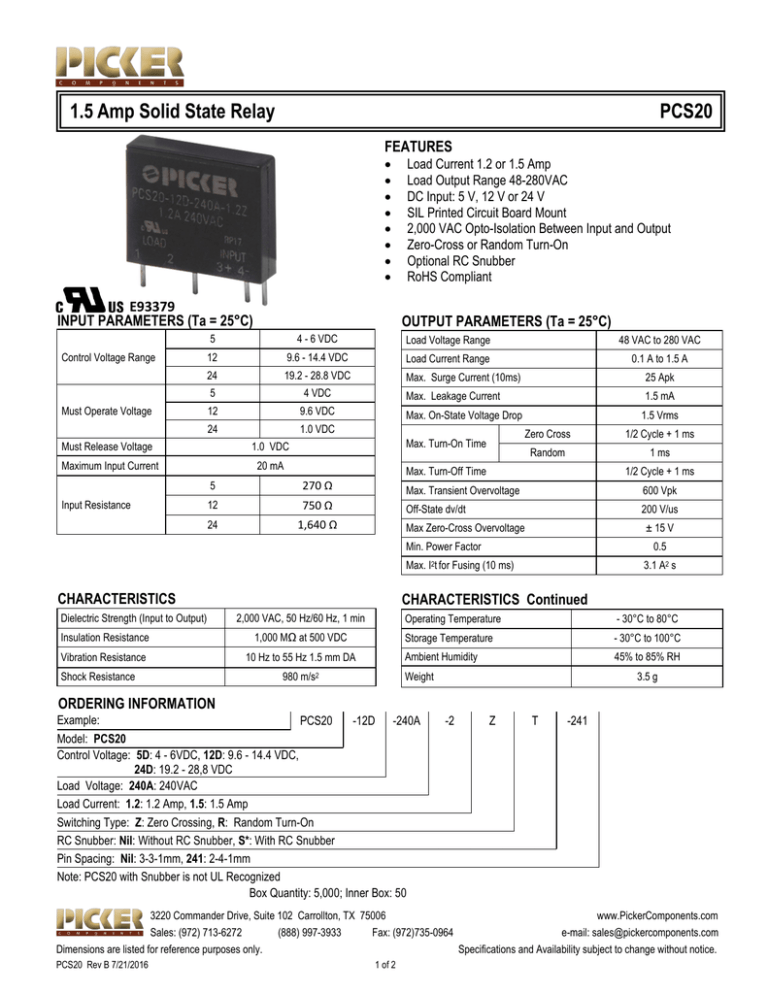
1.5 Amp Solid State Relay PCS20 FEATURES E93379 INPUT PARAMETERS (Ta = 25°C) OUTPUT PARAMETERS (Ta = 25°C) 5 Control Voltage Range Must Operate Voltage 4 - 6 VDC Load Voltage Range 48 VAC to 280 VAC 12 9.6 - 14.4 VDC Load Current Range 0.1 A to 1.5 A 24 19.2 - 28.8 VDC Max. Surge Current (10ms) 25 Apk 5 4 VDC Max. Leakage Current 1.5 mA 12 9.6 VDC 24 1.0 VDC Must Release Voltage 1.0 VDC Maximum Input Current 20 mA Input Resistance Load Current 1.2 or 1.5 Amp Load Output Range 48-280VAC DC Input: 5 V, 12 V or 24 V SIL Printed Circuit Board Mount 2,000 VAC Opto-Isolation Between Input and Output Zero-Cross or Random Turn-On Optional RC Snubber RoHS Compliant Max. On-State Voltage Drop 1.5 Vrms Zero Cross Max. Turn-On Time Random 1/2 Cycle + 1 ms 1 ms Max. Turn-Off Time 1/2 Cycle + 1 ms 5 270 Ω Max. Transient Overvoltage 600 Vpk 12 750 Ω Off-State dv/dt 200 V/us 24 1,640 Ω Max Zero-Cross Overvoltage ± 15 V Min. Power Factor Max. CHARACTERISTICS Dielectric Strength (Input to Output) 0.5 Fusing (10 ms) 3.1 A2 s CHARACTERISTICS Continued 2,000 VAC, 50 Hz/60 Hz, 1 min Insulation Resistance 1,000 MΩ at 500 VDC Vibration Resistance 10 Hz to 55 Hz 1.5 mm DA Shock Resistance I2t for Operating Temperature - 30°C to 80°C Storage Temperature - 30°C to 100°C Ambient Humidity 45% to 85% RH Weight 980 m/s2 3.5 g ORDERING INFORMATION Example: PCS20 -12D -240A Model: PCS20 Control Voltage: 5D: 4 - 6VDC, 12D: 9.6 - 14.4 VDC, 24D: 19.2 - 28,8 VDC Load Voltage: 240A: 240VAC Load Current: 1.2: 1.2 Amp, 1.5: 1.5 Amp Switching Type: Z: Zero Crossing, R: Random Turn-On RC Snubber: Nil: Without RC Snubber, S*: With RC Snubber Pin Spacing: Nil: 3-3-1mm, 241: 2-4-1mm Note: PCS20 with Snubber is not UL Recognized Box Quantity: 5,000; Inner Box: 50 -2 Z T -241 3220 Commander Drive, Suite 102 Carrollton, TX 75006 www.PickerComponents.com Sales: (972) 713-6272 (888) 997-3933 Fax: (972)735-0964 e-mail: sales@pickercomponents.com Dimensions are listed for reference purposes only. Specifications and Availability subject to change without notice. PCS20 Rev B 7/21/2016 1 of 2 PCS20 PCS20 PRECAUTIONS 1. 2. 3. 4. 5. 6. Maximum Soldering Temperatures: 260°C for a maximum of 10 seconds or 350°C for a maximum of 5 seconds. The SSR case serves to dissipate heat. Install the relays so that they are adequately ventilated. If poor ventilation is unavoidable, the load current must be reduced. Please refer to the curve of "Max. Load current Vs. Ambient Temperature". The input circuitry does not incorporate a circuit protecting the SSR from being damaged due to a reversed connection. Make sure that the polarity and the input and output are correct when connecting. If the output transient voltage exceeds the nominal value a varistor should be mounted on the SSR output terminals in parallel to prevent a breakdown of the triac output junction. The result could be a permanent short of the output. The recommended varistor voltage 470V. When using the relay in phase control applications, at a phase control angle close to 180 degrees the relay's input signal will turn off at the trailing edge of the AC sine wave. The phase delay must be limited to end 200us before AC zero cross. This assures that the relay has time to switch off. Shorter times may cause loss of control at the following half cycle. Please do not use the relay beyond the descriptions in the Data Sheet. 7. Terminal Arrangement DIMENSIONS (mm/inches) (241): CHARACTERISTIC CURVES 3220 Commander Drive, Suite 102 Carrollton, TX 75006 www.PickerComponents.com Sales: (972) 713-6272 (888) 997-3933 Fax: (972)735-0964 e-mail: sales@pickercomponents.com Dimensions are listed for reference purposes only. Specifications and Availability subject to change without notice. PCS20 Rev B 7/21/2016 2 of 2


