CK20
20 GHz Clock Phase Shifter
PRELIMINARY
Product Information
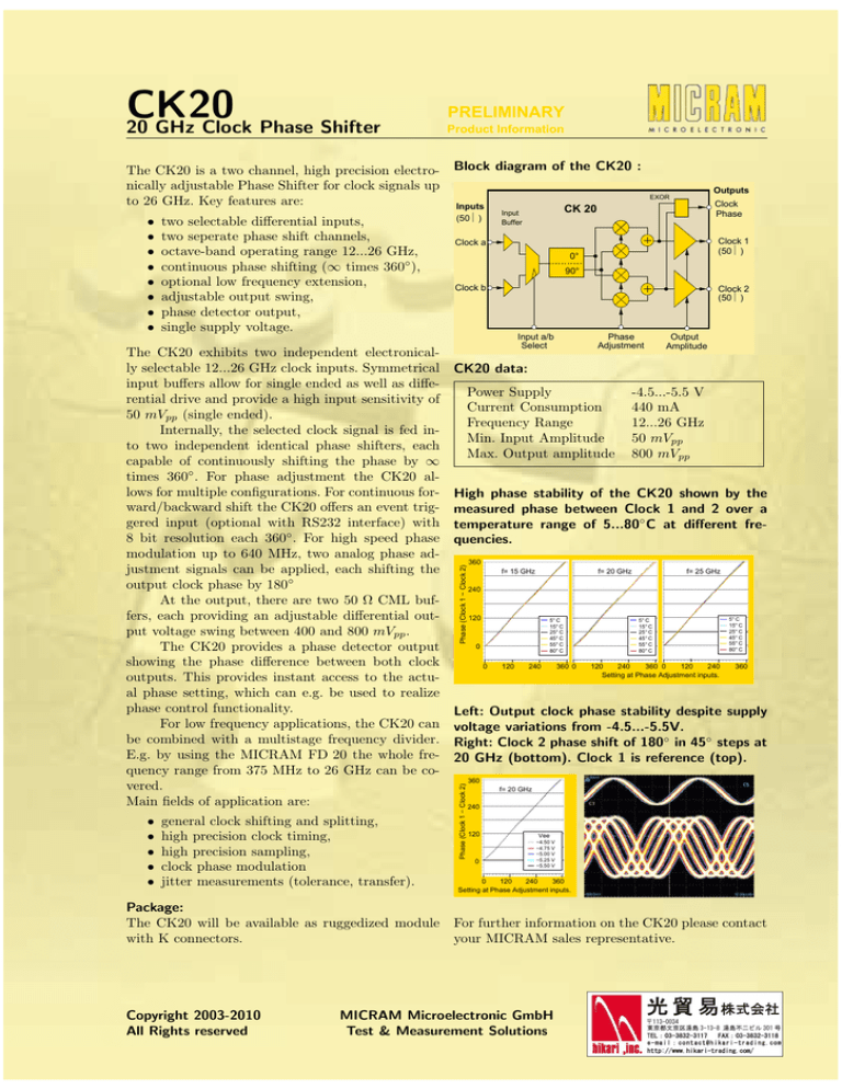
The CK20 is a two channel, high precision electro- Block diagram of the CK20 :
nically adjustable Phase Shifter for clock signals up
to 26 GHz. Key features are:
Inputs
The CK20 exhibits two independent electronically selectable 12...26 GHz clock inputs. Symmetrical
input buffers allow for single ended as well as differential drive and provide a high input sensitivity of
50 mVpp (single ended).
Internally, the selected clock signal is fed into two independent identical phase shifters, each
capable of continuously shifting the phase by ∞
times 360◦ . For phase adjustment the CK20 allows for multiple configurations. For continuous forward/backward shift the CK20 offers an event triggered input (optional with RS232 interface) with
8 bit resolution each 360◦ . For high speed phase
modulation up to 640 MHz, two analog phase adjustment signals can be applied, each shifting the
output clock phase by 180◦
At the output, there are two 50 Ω CML buffers, each providing an adjustable differential output voltage swing between 400 and 800 mVpp .
The CK20 provides a phase detector output
showing the phase difference between both clock
outputs. This provides instant access to the actual phase setting, which can e.g. be used to realize
phase control functionality.
For low frequency applications, the CK20 can
be combined with a multistage frequency divider.
E.g. by using the MICRAM FD 20 the whole frequency range from 375 MHz to 26 GHz can be covered.
Main fields of application are:
•
•
•
•
•
general clock shifting and splitting,
high precision clock timing,
high precision sampling,
clock phase modulation
jitter measurements (tolerance, transfer).
Clock
Phase
CK 20
Input
Buffer
(50Ω )
Clock 1
(50Ω )
Clock a
0°
90°
Clock b
Clock 2
(50Ω )
Input a/b
Select
Phase
Adjustment
Output
Amplitude
CK20 data:
Power Supply
Current Consumption
Frequency Range
Min. Input Amplitude
Max. Output amplitude
-4.5...-5.5 V
440 mA
12...26 GHz
50 mVpp
800 mVpp
High phase stability of the CK20 shown by the
measured phase between Clock 1 and 2 over a
temperature range of 5...80◦ C at different frequencies.
Phase (Clock 1 − Clock 2)
two selectable differential inputs,
two seperate phase shift channels,
octave-band operating range 12...26 GHz,
continuous phase shifting (∞ times 360◦ ),
optional low frequency extension,
adjustable output swing,
phase detector output,
single supply voltage.
360
f= 15 GHz
f= 20 GHz
f= 25 GHz
240
120
5°C
15°C
25°C
45°C
55°C
80°C
0
0
120
240
360 0
5°C
15°C
25°C
45°C
55°C
80°C
240
120
120
240
360 0
Setting at Phase Adjustment inputs.
5°C
15°C
25°C
45°C
55°C
80°C
360
Left: Output clock phase stability despite supply
voltage variations from -4.5...-5.5V.
Right: Clock 2 phase shift of 180◦ in 45◦ steps at
20 GHz (bottom). Clock 1 is reference (top).
Phase (Clock 1 − Clock 2)
•
•
•
•
•
•
•
•
Outputs
EXOR
360
f= 20 GHz
240
120
0
Vee
−4.50 V
−4.75 V
−5.00 V
−5.25 V
−5.50 V
120
0
240
360
Setting at Phase Adjustment inputs.
Package:
The CK20 will be available as ruggedized module For further information on the CK20 please contact
with K connectors.
your MICRAM sales representative.
Copyright 2003-2010
All Rights reserved
MICRAM Microelectronic GmbH
Test & Measurement Solutions
www.micram.com
Tel.: +49-234-9708-300


