IJSTE - International Journal of Science Technology & Engineering | Volume 2 | Issue 10 | April 2016
ISSN (online): 2349-784X
Simulation of Closed Loop Control of Buck
Converter Fed DC Motor Drive
Prof. Mr. Sagar Lanjewar
Department of Electrical Engineering
RGCER, Nagpur
Prof. Mr. Chetan Bhale
Department of Electrical Engineering
RGCER, Nagpur
Prof. Mr. Rajesh Rane
Department of Electrical Engineering
RGCER, Nagpur
Prof. Mr. Yogesh Godhwani
Department of Electrical Engineering
PCEM, Raipur
Abstract
Speed control of separately excited dc motor is carried out by varying the armature voltage for below rated speed and by varying
field flux to achieve speed above the rated speed. The firing circuit of chopper receives signal from controller and variable voltage
is given to the armature of dc motor according to the desired speed value. There are two controllers we are using here one is speed
controller and other is current controller. Both controllers are of proportional -integral type. The reason behind using PI type
controller is it removes the delay and provide fast control. Now the simulation of model is done and analyzed in MATLAB
(Simulink) under varying speed and torque condition.
Keywords: Close Loop System, PI Controller, Modelling of Speed Control of DC Motor
________________________________________________________________________________________________________
I.
INTRODUCTION
An electrical drive consists of electric motors, its power controller and energy transmitting shaft. In modern electric drive system
power electronic converters are used as power controller. Electric drives are mainly of two types: DC drives and AC drives. The
two types differ from each other in that the power supply in DC drives is provided by DC motor and power supply in AC drives is
provided by AC motor.
DC drives are widely used in applications requiring adjustable speed control, frequent starting, good speed regulation, braking and
reversing. Some important applications are paper mills, rolling mills, mine winders, hoists, printing presses, machine tools, traction,
textile mills, excavators and cranes.
DC motors are used extensively in adjustable speed drives and position control system. The speed of DC motors can be adjusted
above or below rated speed. Their speed above rated speed is controlled by field flux control and speed below rated speed is
controlled by armature voltage. DC motors are widely used in industry because of its low cost, less complex control structure and
wide range of speed and torque. There are various methods of speed control of DC drives – armature voltage control, field flux
control and armature resistance control.
For controlling the speed and current of DC motor, speed and current controllers are used. The main work of controller is to
minimize the error and the error is calculated by comparing output value with the set point.
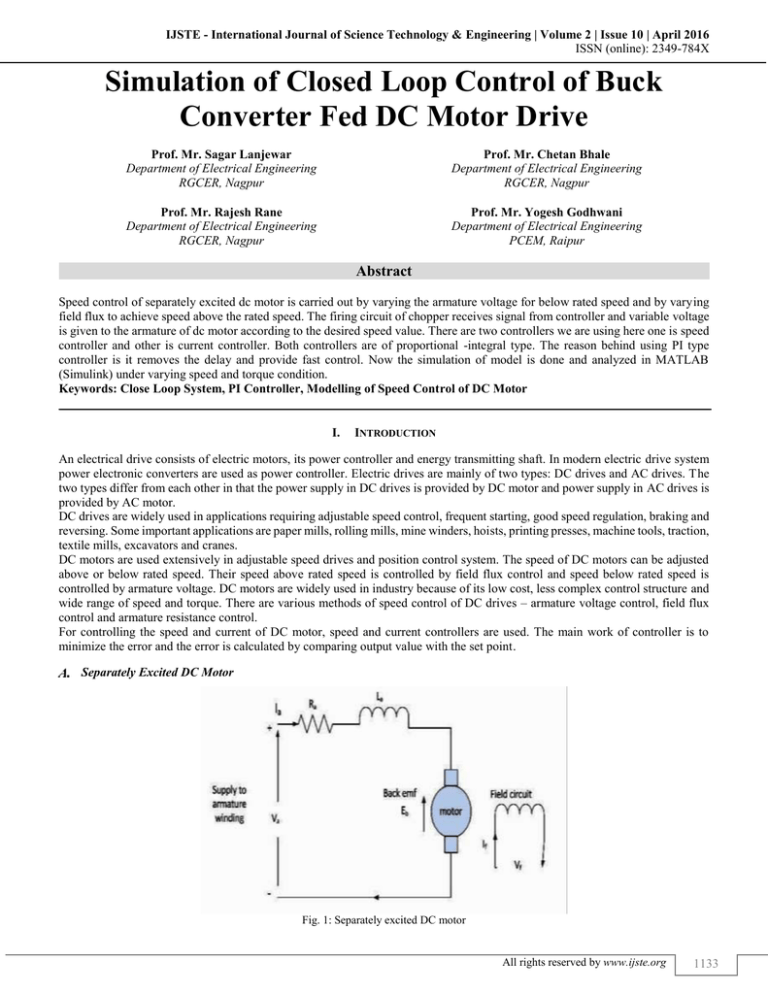
Separately Excited DC Motor
Fig. 1: Separately excited DC motor
All rights reserved by www.ijste.org
1133
Simulation of Closed Loop Control of Buck Converter Fed DC Motor Drive
(IJSTE/ Volume 2 / Issue 10 / 204)
Separately excited dc motor has field and armature winding with separate supply voltage. Field winding supplies field flux to
armature. When DC voltage is applied to motor, current is fed to the armature winding through brushes and commutator. Since
rotor is placed in magnetic field and it is carrying current also. So motor will develop a back emf and a torque to balance load
torque at particular speed.
Mathematical Analysis of Separately Excited DC Motor
When a separately excited dc motor is excited by a field current of If and an armature current of Ia flows in the circuit, the motor
develops a back EMF and a torque to balance the load torque at a particular speed. The field current If is independent of the
armature current Ia. Each winding is supplied separately. Any change in the armature current has no effect on the field current.
The If is generally much less than the Ia.
In the above Figure Suppose
Va is the armature voltage in volt, Ia is the armature current in ampere, Eg is the motor back emf in volt, La is the armature
inductance in Henry, Ra is the armature resistance in ohm.
II. CHOPPER
Introduction
A chopper is a static power electronic device which converts fixed dc input voltage to a variable dc output voltage. Chopper
systems offer smooth control, high efficiency, faster response and regeneration facility. The power semiconductor devices used
for a chopper circuit can be force commutated thyristor, BJT, MOSFET, IGBT and GTO. These devices are generally represented
by a switch. When the switch is OFF, no current will flow. Current flows through the load when switch is ON.
Principle of Chopper Operation
A chopper is a high speed “on" or “off” semiconductor switch. It connects source to load and load and disconnect the load from
source at a fast speed. A constant dc supply of magnitude Vs is given as input voltage and let its output voltage across load be Vo.
For the sake of highlighting the principle of chopper operation, the circuitry used for controlling the on, off periods is not shown.
During the period Ton, chopper is on and load voltage is equal to source voltage Vs. During the period Toff, chopper is off, load
voltage is zero. In this manner, a chopped dc voltage is produced at the load terminals.
Fig. 2: Chopper circuit diagram and its voltage and current waveform
Average Voltage = Vo = (Ton/Ton+Toff) *Vs Vo= (Ton/T)*Vs = α *Vs
Also, Vo = f*Ton*Vs
T = Ton + Toff
α = Ton / Toff = Chopping Period
f = 1/ T
Vo = f* Ton * Vs
Let Vo be the average voltage, Ton is ON time, Toff is OFF time, T is chopping period, and Vs is input voltage and α is duty
cycle. The average output voltage Vo can be controlled by varying duty cycle. There are various control strategies for varying
duty cycle. They are time ratio Control and current-limit control.
All rights reserved by www.ijste.org
1134
Simulation of Closed Loop Control of Buck Converter Fed DC Motor Drive
(IJSTE/ Volume 2 / Issue 10 / 204)
III. MATLAB SIMULATIONS, RESULTS AND ANALYSIS
Fig. 3: Simulation model of chopper fed DC Motor in closed loop system
Rating of the elements used in the above simulation:
Dc voltage source – 280 V
Rating of dc machine – 5 HP, 240 V
Torque – 5 N-M, Field voltage – 240 V
Reference speed – 120 rad/sec
Results and Graphs
Fig. 4: Simulation output of DC chopper for DC Machine in closed loop system (Reference speed= 120rad/s)
All rights reserved by www.ijste.org
1135
Simulation of Closed Loop Control of Buck Converter Fed DC Motor Drive
(IJSTE/ Volume 2 / Issue 10 / 204)
Fig. 5: Simulation of Chopper fed DC Motor (Reference speed=180 rad/s)
IV. CONCLUSION
The speed of the motor has been successfully controlled by using chopper as a converter and proportional integral type speed and
current controller based on closed loop model of DC motor. Initially a model for speed control of DC motor is considered and
requirements of current controller is studied. Then a generalized modeling of DC motor is done. Now the simulation is done in
MATLAB under varying load conditions. The results are also studied and analyzed under above conditions. The model shows
good results under all conditions employed during simulation. Since the simulation of speed control of DC motor has been studied
done. We can also implement it in hardware to observe actual feasibility. Here speed control of dc motor is done for rated and
below rated speed.
REFERENCES
[1]
[2]
[3]
[4]
[5]
[6]
[7]
Paper of chopper based speed control of DC Motor by Krunal Shah (2015).
Power Electronics by K.B. Khanchandani.
DC Machines by Ashfaq Hussain.
Paper of control of DC Motor using chopper by Shri Marripudi Laxmi Deepak(May 2014).
Paper of speed control of DC Series motor by using Power MOSFET chopper by Abdullah Omran Ali(2010).
Speed control of DC motor using chopper submitted by B. D. Sethy & A.K.Sinha from NIT (ODISHA).
BOSE B.K Power Electronics and motor drives recent technology advances, IEEE 2002, p22-25.
All rights reserved by www.ijste.org
1136


