LETTER
doi:10.1038/nature13883
Passive radiative cooling below ambient air
temperature under direct sunlight
Aaswath P. Raman1, Marc Abou Anoma2, Linxiao Zhu3, Eden Rephaeli1 & Shanhui Fan1
Cooling is a significant end-use of energy globally and a major driver
of peak electricity demand. Air conditioning, for example, accounts
for nearly fifteen per cent of the primary energy used by buildings in
the United States1. A passive cooling strategy that cools without any
electricity input could therefore have a significant impact on global
energy consumption. To achieve cooling one needs to be able to reach
and maintain a temperature below that of the ambient air. At night,
passive cooling below ambient air temperature has been demonstrated
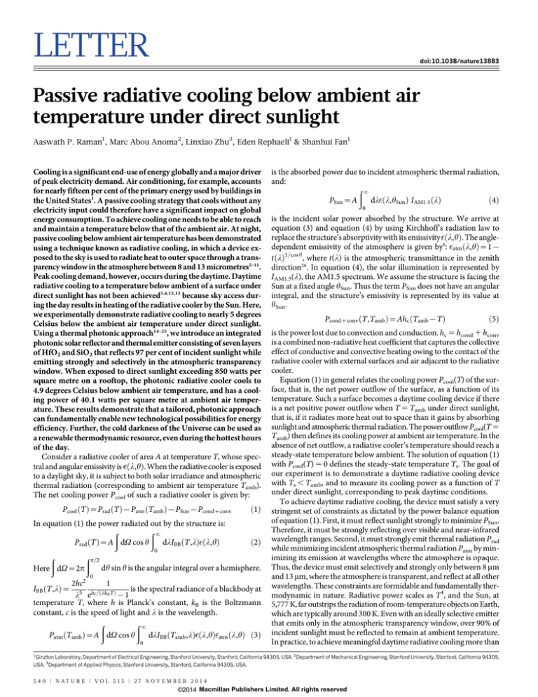
using a technique known as radiative cooling, in which a device exposed to the sky is used to radiate heat to outer space through a transparency window in the atmosphere between 8 and 13 micrometres2–11.
Peak cooling demand, however, occurs during the daytime. Daytime
radiative cooling to a temperature below ambient of a surface under
direct sunlight has not been achieved3,4,12,13 because sky access during the day results in heating of the radiative cooler by the Sun. Here,
we experimentally demonstrate radiative cooling to nearly 5 degrees
Celsius below the ambient air temperature under direct sunlight.
Using a thermal photonic approach14–25, we introduce an integrated
photonic solar reflector and thermal emitter consisting of seven layers
of HfO2 and SiO2 that reflects 97 per cent of incident sunlight while
emitting strongly and selectively in the atmospheric transparency
window. When exposed to direct sunlight exceeding 850 watts per
square metre on a rooftop, the photonic radiative cooler cools to
4.9 degrees Celsius below ambient air temperature, and has a cooling power of 40.1 watts per square metre at ambient air temperature. These results demonstrate that a tailored, photonic approach
can fundamentally enable new technological possibilities for energy
efficiency. Further, the cold darkness of the Universe can be used as
a renewable thermodynamic resource, even during the hottest hours
of the day.
Consider a radiative cooler of area A at temperature T, whose spectral and angular emissivity is ðl,hÞ. When the radiative cooler is exposed
to a daylight sky, it is subject to both solar irradiance and atmospheric
thermal radiation (corresponding to ambient air temperature Tamb).
The net cooling power Pcool of such a radiative cooler is given by:
Pcool ðT Þ~Prad ðT Þ{Patm ðTamb Þ{PSun {Pcondzconv
In equation (1) the power radiated out by the structure is:
ð
ð?
dlIBB ðT,lÞ ðl,hÞ
Prad ðT Þ~A dV cos h
ð1Þ
ð2Þ
0
ð
ð p=2
dh sin h is the angular integral over a hemisphere.
Here dV~2p
0
2hc2
1
is the spectral radiance of a blackbody at
IBB ðT,lÞ~ 5 hc=ðlk T Þ
B
{1
l e
temperature T, where h is Planck’s constant, kB is the Boltzmann
constant, c is the speed of light and l is the wavelength.
ð
ð?
Patm ðTamb Þ~A dV cos h
dlIBB ðTamb ,lÞ ðl,hÞ atm ðl,hÞ ð3Þ
0
is the absorbed power due to incident atmospheric thermal radiation,
and:
ð?
dl ðl,hSun Þ IAM1:5 ðlÞ
ð4Þ
PSun ~A
0
is the incident solar power absorbed by the structure. We arrive at
equation (3) and equation (4) by using Kirchhoff’s radiation law to
replace the structure’s absorptivity with its emissivity ðl,hÞ. The angledependent emissivity of the atmosphere is given by6: atm ðl,hÞ~1{
t ðlÞ1=cos h , where t(l) is the atmospheric transmittance in the zenith
direction26. In equation (4), the solar illumination is represented by
IAM1.5(l), the AM1.5 spectrum. We assume the structure is facing the
Sun at a fixed angle hSun. Thus the term PSun does not have an angular
integral, and the structure’s emissivity is represented by its value at
hSun.
Pcondzconv ðT,Tamb Þ~Ahc ðTamb {T Þ
ð5Þ
is the power lost due to convection and conduction. hc 5 hcond 1 hconv
is a combined non-radiative heat coefficient that captures the collective
effect of conductive and convective heating owing to the contact of the
radiative cooler with external surfaces and air adjacent to the radiative
cooler.
Equation (1) in general relates the cooling power Pcool(T) of the surface, that is, the net power outflow of the surface, as a function of its
temperature. Such a surface becomes a daytime cooling device if there
is a net positive power outflow when T 5 Tamb under direct sunlight,
that is, if it radiates more heat out to space than it gains by absorbing
sunlight and atmospheric thermal radiation. The power outflow Pcool(T 5
Tamb) then defines its cooling power at ambient air temperature. In the
absence of net outflow, a radiative cooler’s temperature should reach a
steady-state temperature below ambient. The solution of equation (1)
with Pcool(T) 5 0 defines the steady-state temperature Ts. The goal of
our experiment is to demonstrate a daytime radiative cooling device
with Ts , Tamb, and to measure its cooling power as a function of T
under direct sunlight, corresponding to peak daytime conditions.
To achieve daytime radiative cooling, the device must satisfy a very
stringent set of constraints as dictated by the power balance equation
of equation (1). First, it must reflect sunlight strongly to minimize PSun.
Therefore, it must be strongly reflecting over visible and near-infrared
wavelength ranges. Second, it must strongly emit thermal radiation Prad
while minimizing incident atmospheric thermal radiation Patm by minimizing its emission at wavelengths where the atmosphere is opaque.
Thus, the device must emit selectively and strongly only between 8 mm
and 13 mm, where the atmosphere is transparent, and reflect at all other
wavelengths. These constraints are formidable and fundamentally thermodynamic in nature. Radiative power scales as T4, and the Sun, at
5,777 K, far outstrips the radiation of room-temperature objects on Earth,
which are typically around 300 K. Even with an ideally selective emitter
that emits only in the atmospheric transparency window, over 90% of
incident sunlight must be reflected to remain at ambient temperature.
In practice, to achieve meaningful daytime radiative cooling more than
1
Ginzton Laboratory, Department of Electrical Engineering, Stanford University, Stanford, California 94305, USA. 2Department of Mechanical Engineering, Stanford University, Stanford, California 94305,
USA. 3Department of Applied Physics, Stanford University, Stanford, California 94305, USA.
5 4 0 | N AT U R E | VO L 5 1 5 | 2 7 NO V E M B E R 2 0 1 4
©2014 Macmillan Publishers Limited. All rights reserved
LETTER RESEARCH
shield. As can be seen in the two-dimensional schematic of the apparatus
in Fig. 1c, the radiative cooler is thus suspended in a relatively wellsealed air pocket. Such an air pocket design represents a key innovation in the experimental demonstration of daytime radiative cooling:
note that our sample is far smaller than the surrounding roof. This design
aims to ensure that any surface in immediate contact with the air pocket
or the sample will heat up minimally due to solar irradiance. Finally, to
ensure peak sunlight irradiance of up to 890 W m22 on the radiative
cooler during the winter months in which testing was conducted, the
entire apparatus is tilted 30u towards the south. This experimental constraint reduces sky access for the purposes of thermal radiation, so for
the same setup, better cooling performance would be expected if one were
to operate the cooler without the tilt.
We use a photonic approach to meet these stringent demands of selective thermal emission in the mid-infrared, and strong solar reflection. An extensive numerical optimization scheme (see Methods) is used
to achieve the photonic design schematically shown in Fig. 1d with a
scanning electron microscope cross-section. The photonic radiative
cooler consists of seven alternating layers of hafnium dioxide (HfO2)
and silicon dioxide (SiO2) of varying thicknesses, on top of 200 nm of
silver (Ag), which are all deposited on top of a 200-mm silicon wafer.
The bottom four layers of HfO2 and SiO2 have thicknesses that are less
than 100 nm and assist in optimizing solar reflection in a manner akin
to that achievable using periodic one-dimensional photonic crystals.
HfO2 serves as a high-index material that also presents low ultraviolet
absorption, a useful feature when optimizing for solar reflectance, while
SiO2 is optically transparent and is the low-index layer. The use of HfO2
is, however, not essential, and can be replaced with titanium dioxide
(TiO2), which is less expensive. The top three layers are much thicker
and are primarily responsible for thermal radiation from the cooler,
94% of sunlight must be reflected, especially given variation in atmospheric conditions across different geographic regions27. This is particularly challenging when combined with the goal of emitting strongly
and selectively in the atmospheric window. Previous approaches using
metallic reflectors and conventional thermal emitters with reflective cover
foils have thus proved to be insufficient to achieve cooling under direct
sunlight. Finally, the radiative cooler must be well sealed from its environment to minimize hc and in turn Pcond1conv. This constraint presents an experimental design challenge during the daytime given that
most surfaces that might be in contact with the radiative cooler will
themselves heat up when exposed to sunlight and transfer this added
heat to the cooler.
A previous paper presented a theoretical design of a photonic structure capable of satisfying the emission and reflection requirements for
cooling14. The design there involved the use of a complex two-dimensional
photonic crystal that would require photolithography. Here we introduce and numerically optimize an alternative theoretical design based
on one-dimensional photonic films that is more amenable to large-scale
fabrication, and experimentally realize it. Furthermore, we design and
build an apparatus that minimizes heat load on the radiative cooler,
allowing us to observe below-ambient cooling in the daytime for the
first time.
The rooftop measurement apparatus that minimizes hc, and is used
to experimentally demonstrate radiative cooling under direct sunlight,
is shown in Fig. 1a. The design of the apparatus, shown schematically
in Fig. 1b and c, reduces both convection and conduction to the radiative
cooler under peak solar irradiance. The radiative cooling surface, deposited on a 200-mm silicon wafer, is placed on a polystyrene pedestal which
is supported by a clear acrylic box (see Methods for details). A clear 12.5-mm
polyethylene film lies above the sample as an infrared-transparent wind
a
b
Selectively emit
thermal radiation
Reflect
sunlight
Roof
Cooler
30° tilt
c
Low-density polyethylene
Aluminized Mylar
Clear
acrylic
Wood
frame
d
Photonic radiative cooler
Air pocket
Polystyrene
Aluminized Mylar
SiO2
230 nm
HfO2
485 nm
SiO2
688 nm
Ag
Ti
200 nm
20 nm
Si
Figure 1 | Rooftop apparatus and photonic radiative cooler. a, Photo of the
apparatus and radiative cooler on the test rooftop in Stanford, California.
b, Three-dimensional schematic of the apparatus and radiative cooler,
showing the general mode of operation of the radiative cooler. The apparatus is
designed to minimize conductive and convective heat exchange to the
cooler. c, Cut-out schematic of the apparatus through the middle, showing
how an air pocket is created around the radiative cooler. Surfaces adjacent to
HfO2
13 nm
SiO2
73 nm
HfO2
34 nm
SiO2
54 nm
this air pocket heat up minimally due to incident solar irradiance and therefore
minimize the heat load on the air inside the pocket. Mylar is polyethylene
terephthalate. d, Scanning electron microscope image of the photonic radiative
cooler that is designed, implemented and tested in our experiments. It consists
of seven layers of HfO2 and SiO2, whose thicknesses are defined by extensive
numerical optimization (see Methods), on top of 200 nm of Ag, a 20-nm-thick
Ti adhesion layer, and a 750-mm-thick, 200-mm-diameter Si wafer substrate.
2 7 NO V E M B E R 2 0 1 4 | VO L 5 1 5 | N AT U R E | 5 4 1
©2014 Macmillan Publishers Limited. All rights reserved
RESEARCH LETTER
through a combination of material properties and interference effects.
SiO2 has a strong peak in its absorptivity near 9 mm due to its phonon–
polariton resonance. HfO2 also presents non-zero absorption and hence
emission in the 8–13 mm wavelength range28. The combination of all these
layers results in a macroscopically planar and integrated structure that
collectively achieves high solar reflectance and strong thermal emission.
The photonic radiative cooler’s absorptivity/emissivity spectrum is
experimentally characterized and shown in Fig. 2. The cooler shows minimal absorption when integrated from 300 nm to 4 mm, where the solar
spectrum is present, in Fig. 2a, reflecting 97% of incident solar power
at near-normal incidence. In Fig. 2b we observe that the cooler has strong
and remarkably selective emissivity in the atmospheric window between
8 mm and 13 mm. Moreover, the photonic radiative cooler’s thermal emissivity persists to large angles (see Extended Data Fig. 1), a useful feature
to maximize radiated power Prad, a hemispherically integrated quantity—
see equation (2)—and reminiscent of the behaviour of hyperbolic metamaterials29. Photonic design fundamentally enables these spectral properties, which in turn are essential to achieving below-ambient radiative
cooling. This spectral behaviour, and below-ambient cooling, is not
achievable using these materials individually with conventional metallic reflectors.
We demonstrate the performance of the photonic radiative cooler on
a clear winter day in Stanford, California, by exposing it to the sky on a
building roof during daylight hours and comparing its steady-state temperature to the ambient air temperature. As shown in the temperature
data of Fig. 3a, immediately after the sample is exposed to the environment (shortly before 10:00 local time in Fig. 3a), its temperature drops
to approximately 4u to 5u Celsius below the ambient air temperature,
even though significant solar irradiance is already incident on the sample. This is a key signature of radiative cooling, and a counterintuitive
result during the day: we typically think of surfaces increasing their temperature when removed from the shade and exposed to the Sun during
the day. We observe the photonic radiative cooler’s temperature for over
five hours under direct sunlight. Over 800 W m22 of solar power is incident on the sample for three of the five hours. The cooler maintains a
steady-state temperature substantially below the air temperature over
the entire day, and is 4.9uC 6 0.15uC below the air temperature between 13:00 and 14:00 (local time) when the solar irradiance is in the
range 800–870 W m22. To illustrate the significance of this result, we
compare in Fig. 3b the photonic radiative cooler’s performance against
200-mm wafers in identical apparatuses coated with conventional materials: carbon black paint and aluminium. The black paint reaches near
80u C, which is more than 60 uC above the ambient air temperature,
while the aluminium reaches nearly 40u C, which is 20u C above the ambient air temperature. Typical roofing material has strong solar absorption and hence significantly heats up under direct sunlight, as emulated
by the black paint result here. Also, one still sees very strong heating
with an aluminium film, even though it provides relatively strong solar
reflection.
We next characterize the photonic radiative cooler’s cooling power.
We allow its temperature to reach the previously achieved steady-state
value under peak sunlight conditions of nearly 900 W m22. We then input heat to the cooler in steps over the course of one hour and observed
Exposed to sky
900
a
Temperature (°C)
Emissivity/absorptivity
0.75
Ambient air temperature
500
0.5
0.25
AM1.5 solar
spectrum
7.5
10:00
1
1.5
Wavelength (μm)
2
11:00
12:00
13:00
Time of day
14:00
900
b
Temperature (°C)
80
0.75
0.5
800
500
50
Aluminium
30
5
8
10
13
Wavelength (μm)
20
Figure 2 | Emissivity/absorptivity of the photonic radiative cooler from the
ultraviolet to the mid-infrared. a, Measured emissivity/absorptivity at 5u
angle of incidence of the photonic radiative cooler over optical and nearinfrared wavelengths using an unpolarized light source, with the AM1.5 solar
spectrum plotted for reference. The cooler reflects 97% of incident solar
radiation. b, Measured emissivity/absorptivity of the cooler at 5u angle of
incidence over mid-infrared wavelengths using an unpolarized light source,
with a realistic atmospheric transmittance model plotted for reference26.
The photonic cooler achieves strong selective emission within the
atmospheric window.
250
Ambient air
20
0
10:00
Atmospheric
transmittance
700
Black paint
10
0.25
0
15:00
Exposed to sky
2.5
1
0
2.5
Photonic radiative cooler 250
temperature
10
Photonic radiative cooler
11:00
12:00
13:00
Time of day
14:00
Solar irradiance (W m–2)
Emissivity/absorptivity
700
15
12.5
0
0.3 0.5
b
800
17.5
1
Solar irradiance (W m–2)
a
0
15:00
Figure 3 | Steady-state temperature of photonic radiative cooler. a, Rooftop
measurement of the photonic radiative cooler’s performance (blue) against
ambient air temperature (black) on a clear winter day in Stanford, California.
The photonic radiative cooler immediately drops below ambient once
exposed to the sky, and achieves a steady-state temperature Ts of
4.9 uC 6 0.15 uC below ambient for over one hour where the solar irradiance
incident on it (green) ranges from 800 W m22 to 870 W m22. b, Comparing
the photonic radiative cooler’s performance against two reference roofing
materials: black paint and aluminium. The paint reaches a temperature up to
80 uC, or 60 uC above ambient, while the aluminium reaches nearly 40 uC,
or 20 uC above ambient. Only the photonic cooler stays well below ambient
under direct solar irradiance.
5 4 2 | N AT U R E | VO L 5 1 5 | 2 7 NO V E M B E R 2 0 1 4
©2014 Macmillan Publishers Limited. All rights reserved
LETTER RESEARCH
the cooler’s temperature at each step, as shown in Fig. 4a. With each
increase of heat input, the temperature of the cooler rises to a new steady
state. We plot the temperature of the cooler as a function of heat power
in Fig. 4b. The temperature of the cooler reaches ambient temperature
with an input heat power of 40.1 6 4.1 W m22, indicating that substantial cooling power is available from this device. We next develop a theoretical model of our photonic cooler. This model is based on equation
(1), where we use the spectral data of Fig. 2, as well as a model of the
atmospheric transmittance26 (see Methods), and a model for the conductive and convective losses of the apparatus, that together yield a value
of hc 5 6.9 W m22 K21 (see Methods and Extended Data Fig. 2). The
theoretical model agrees excellently with the experimental data (Fig. 4b).
The model can also be used to predict the steady-state temperature and
power balance of the photonic radiative cooler as a function of time,
and as compared against the observed performance of the sample under
both daytime and night-time conditions (Extended Data Fig. 3). Moreover, the model indicates that lower steady-state temperatures can be
reached by the cooler by reducing convective losses (see Methods). Under
the same atmospheric and solar conditions, but with hc R 0, our device
should achieve a steady-state temperature of 19.5 uC below ambient
(see Extended Data Fig. 2c). Substantial gains in the photonic radiative
cooler’s performance are thus achievable by improved packaging alone.
The below-ambient cooling under peak daylight conditions shown
here presents the possibility for purely passive, water-free approaches
to cooling buildings and vehicles at all hours of the day. A preliminary
analysis indicates that photonic radiative coolers could compete favourably in economic terms against other rooftop renewable energy options
for cooling such as photovoltaic panels but may also work cooperatively
with them (see Methods and Extended Data Fig. 4). A key engineering
challenge will be to minimize parasitic heating of the radiative cooler
from the surroundings while delivering the desired heat load to it efficiently. With the remarkable degree of spectral and thermal control made
possible by photonic approaches, cooling power performance in favourable atmospheric conditions could be improved to more than 100 W m22
(ref. 14). Improving building efficiency with a view towards reducing
the need for active cooling has taken on renewed urgency on our warming planet, where the increase in carbon emissions caused by air conditioning is predicted to be faster than the decline in emissions from
reduced heating30. In off-grid areas of the developing world, achieving
radiative cooling during the daytime offers the opportunity to enable
electricity-free cooling for critical needs like long-term food and medical
supply storage. More broadly, our results point to the largely unexplored
opportunity of using the cold darkness of the Universe as a fundamental renewable thermodynamic resource for improving energy efficiency
here on Earth.
Online Content Methods, along with any additional Extended Data display items
and Source Data, are available in the online version of the paper; references unique
to these sections appear only in the online paper.
Received 23 April; accepted 22 September 2014.
0 5 10 19.7 30.8 34.7 40.1 50.6 60.6
a
0
24
Heat input (W m–2)
900
Solar irradiance
Ambient air
22
20
Radiative cooler
18
Solar irradiance (W m–2)
800
Temperature (°C)
1.
2.
3.
4.
5.
6.
500
16
12:30
13:00
13:30
14:00
7.
8.
Time of day
b
9.
2
Tsample – Tambient (°C)
10.
1
11.
0
–1
12.
–2
−3
13.
−4
14.
−5
0
20
40
60
Cooling power (W m–2)
Figure 4 | Cooling power of photonic radiative cooler. a, Rooftop
measurement of the photonic radiative cooler’s temperature (blue), relative to
ambient air temperature (black), in response to step-wise increasing inputs of
heat (quantity shown at top at the beginning of each time period). For an
input of 40.1 6 4.1 W m22 the radiative cooler reaches ambient air
temperature, where solar irradiance of 860 W m22 is incident on the cooler.
b, The average temperature reached by the cooler over the last two minutes of
each time period in a relative to ambient air temperature (Tsample minus
Tambient) for each associated value of input heat, with error bars defined by
instrument and measurement error (see Methods). The predictions of a
theoretical model for hc 5 6.9 W m22 K21 are shown in the grey band, whose
bounds are set by uncertainty associated with atmospheric transmittance.
15.
16.
17.
18.
19.
20.
21.
22.
Kelso, J. K. (ed.) 2011 Buildings Energy Data Book http://buildingsdatabook.eren.
doe.gov/docs/DataBooks/2011_BEDB.pdf (US Department of Energy, Office of
Energy Efficiency and Renewable Energy, 2011).
Trombe, F. Perspectives sur l’utilisation des rayonnements solaires et terrestres
dans certaines régions du monde. Revue Générale Thermique 6, 1285–1314
(1967).
Catalanotti, S. et al. The radiative cooling of selective surfaces. Sol. Energy 17,
83–89 (1975).
Bartoli, B. et al. Nocturnal and diurnal performances of selective radiators. Appl.
Energy 3, 267–286 (1977).
Granqvist, C. G. & Hjortsberg, A. Surfaces for radiative cooling: silicon monoxide
films on aluminum. Appl. Phys. Lett. 36, 139–141 (1980).
Granqvist, C. G. & Hjortsberg, A. Radiative cooling to low temperatures: general
considerations and application to selectively emitting SiO films. J. Appl. Phys. 52,
4205–4220 (1981).
Berdahl, P., Martin, M. & Sakkal, F. Thermal performance of radiative cooling
panels. Int. J. Heat Mass Transf. 26, 871–880 (1983).
Berdahl, P. Radiative cooling with MgO and/or LiF layers. Appl. Opt. 23, 370–372
(1984).
Orel, B., Gunde, M. & Krainer, A. Radiative cooling efficiency of white pigmented
paints. Sol. Energy 50, 477–482 (1993).
Gentle, A. R. & Smith, G. B. Radiative heat pumping from the earth using surface
phonon resonant nanoparticles. Nano Lett. 10, 373–379 (2010).
Gentle, A., Aguilar, J. & Smith, G. Optimized cool roofs: integrating albedo and
thermal emittance with R-value. Sol. Energy Mater. Sol. Cells 95, 3207–3215
(2011).
Nilsson, T. M. & Niklasson, G. A. Radiative cooling during the day: simulations and
experiments on pigmented polyethylene cover foils. Sol. Energy Mater. Sol. Cells 37,
93–118 (1995).
Nilsson, T. M., Niklasson, G. A. & Granqvist, C. G. A solar reflecting material for
radiative cooling applications: ZnS pigmented polyethylene. Sol. Energy Mater. Sol.
Cells 28, 175–193 (1992).
Rephaeli, E., Raman, A. & Fan, S. Ultrabroadband photonic structures to achieve
high-performance daytime radiative cooling. Nano Lett. 13, 1457–1461 (2013).
Lin, S.-Y. et al. Enhancement and suppression of thermal emission by a threedimensional photonic crystal. Phys. Rev. B 62, R2243–R2246 (2000).
Greffet, J.-J. et al. Coherent emission of light by thermal sources. Nature 416,
61–64 (2002).
Narayanaswamy, A. & Chen, G. Thermal emission control with one-dimensional
metallodielectric photonic crystals. Phys. Rev. B 70, 125101 (2004).
Luo, C., Narayanaswamy, A., Chen, G. & Joannopoulos, J. D. Thermal radiation from
photonic crystals: a direct calculation. Phys. Rev. Lett. 93, 213905 (2004).
Lee, B. J., Fu, C. J. & Zhang, Z. M. Coherent thermal emission from one-dimensional
photonic crystals. Appl. Phys. Lett. 87, 071904 (2005).
Drevillon, J. & Ben-Abdallah, P. Ab initio design of coherent thermal sources.
J. Appl. Phys. 102, 114305 (2007).
Schuller, J., Taubner, T. & Brongersma, M. Optical antenna thermal emitters.
Nature Photon. 3, 658–661 (2009).
Rephaeli, E. & Fan, S. Absorber and emitter for solar thermo-photovoltaic systems
to achieve efficiency exceeding the Shockley-Queisser limit. Opt. Express 17,
15145–15159 (2009).
2 7 NO V E M B E R 2 0 1 4 | VO L 5 1 5 | N AT U R E | 5 4 3
©2014 Macmillan Publishers Limited. All rights reserved
RESEARCH LETTER
23. Wu, C. et al. Metamaterial-based integrated plasmonic absorber/emitter for solar
thermo-photovoltaic systems. J. Opt. 14, 024005 (2012).
24. De Zoysa, M. et al. Conversion of broadband to narrowband thermal emission
through energy recycling. Nature Photon. 6, 535–539 (2012).
25. Lenert, A. et al. A nanophotonic solar thermophotovoltaic device. Nature
Nanotechnol. 9, 126–130 (2014).
26. Berk, A. et al. Modtran5: 2006 update. Proc. SPIE 6233, 62331F (2006).
27. Martin, M. & Berdahl, P. Characteristics of infrared sky radiation in the United
States. Sol. Energy 33, 321–336 (1984).
28. Bright, T., Watjen, J., Zhang, Z., Muratore, C. & Voevodin, A. Optical properties of
HfO2 thin films deposited by magnetron sputtering: from the visible to the
far-infrared. Thin Solid Films 520, 6793–6802 (2012).
29. Jacob, Z. et al. Engineering photonic density of states using metamaterials. Appl.
Phys. B 100, 215–218 (2010).
30. Isaac, M. & van Vuuren, D. P. Modeling global residential sector energy demand for
heating and air conditioning in the context of climate change. Energy Policy 37,
507–521 (2009).
Acknowledgements This work is supported by the Advanced Research Projects
Agency-Energy (ARPA-E), Department of Energy (contract number DE-AR0000316).
We acknowledge discussions with J. Eaton and K. Goodson. Part of this work was
performed at the Stanford Nanofabrication Facility, which is supported by the National
Science Foundation through the NNIN under grant number ECS-9731293, and the
Stanford Nano Center (SNC)/Stanford Nanocharacterization Laboratory (SNL), part of
the Stanford Nano Shared Facilities.
Author Contributions A.P.R. and S.F. envisioned and implemented the experimental
studies, and wrote the manuscript. A.P.R. and M.A.A. built and executed the rooftop
experiments. A.P.R. designed and characterized the radiative cooler. L.Z. and E.R.
provided technical support and conceptual advice.
Author Information Reprints and permissions information is available at
www.nature.com/reprints. The authors declare no competing financial interests.
Readers are welcome to comment on the online version of the paper. Correspondence
and requests for materials should be addressed to A.P.R. (aaswath@stanford.edu) or
S.F. (shanhui@stanford.edu).
5 4 4 | N AT U R E | VO L 5 1 5 | 2 7 NO V E M B E R 2 0 1 4
©2014 Macmillan Publishers Limited. All rights reserved
LETTER RESEARCH
METHODS
31
Photonic design optimization. The needle optimization method is used to determine and optimize the number of layers and layer thicknesses of the photonic radiative cooler. The target metrics chosen for optimization were ideal reflectivity over
the solar spectrum, weighted by the AM1.5 solar spectrum, and ideal emissivity in
the range 8–13 mm. A combination of simulated annealing and quasi-newton methods are used to re-optimize layer thicknesses. Ag is defined to be the substrate
layer, and HfO2 and SiO2 the materials to be used as alternating inserted layers.
Refractive indices and extinction coefficients used in the optimization are derived
from the ellipsometry of the bulk deposited layers of the materials for SiO2 and Ag
from 300 nm to 1,500 nm, with other values for other materials and wavelengths
ranges coming from tabulated references32.
Cooler fabrication and characterization. The photonic radiative cooler was deposited using electron beam evaporation on top of a 750-mm-thick, 200-mm-diameter
silicon wafer by LGA Thin Films. A 20-nm-thick adhesion layer of Ti was first deposited, followed by 200 nm of Ag, and the seven alternating dielectric layers of
HfO2 and SiO2 at the thicknesses shown in Fig. 1d. Thicknesses are monitored
using a quartz crystal monitor during deposition. Depositing a thick layer of HfO2
necessitates multiple cool-downs to prevent overheating due to the high temperatures needed for its evaporation. The reflectance of the cooler was characterized in
the visible and near-infrared using a spectrophotometer (Jasco V-670) with an unpolarized light source and a calibrated high specular reflectance standard (Ocean
Optics STAN-SSH), and is shown in Fig. 2a. In the infrared, a Fourier transform
infrared spectrometer (Thermo Scientific Nicolet 6700) with an unpolarized light
source is used to characterize the cooler’s reflectance with a gold film used as a reflectance standard, as shown in Fig. 2b. A variable-angle accessory (Harrick Seagull)
allows for reflectance measurements at varying angles of incidence from 5u to 85u
(see Extended Data Fig. 1 for data). A scanning electron microscope (FEI Nova
NanoSEM 450) is used to image the layers and is shown in Fig. 1d.
Rooftop measurement. The radiative cooler and reference materials were tested
on the flat roof of a three-storey building (Fig. 1a) in Stanford, California, in midDecember 2013. The Sun’s peak altitude was 30u above the horizon on the days
testing occurred, while the apparatus containing the radiative coolers was placed
on a platform tilted at 30u 6 2u. Thus at maximum solar irradiance hSun 5 30u 6 2u.
The apparatus containing the radiative cooler consists of a wood frame covered
by a layer of aluminized Mylar. The top surface of the frame has a circular 10-inch
aperture. A clear acrylic box with the top side open, and the bottom side containing
a 200-mm aperture is joined and sealed to the underside of the wooden frame’s top
surface. An aluminized Mylar-coated polystyrene pedestal is then inserted through
the acrylic box’s 200-mm aperture, and the radiative cooler is placed on top of the
polystyrene. A 12.5-mm-thick low-density polyethylene film is then used to seal the
top aperture on the wooden frame, and serves as an infrared-transparent wind shield.
This design, schematically represented in Fig. 1c, creates a well-sealed air pocket
around the sample. Surfaces in contact with the air pocket absorb sunlight minimally and thus minimize the heat load on the sample due to external solar heating
of adjacent surfaces and air.
The back-surface of the radiative cooler is instrumented with an adhesive resistance temperature detector sensor with 60.15 uC accuracy mounted at the centre
of the wafer, connected to a data logger (Omega OM-CP-OCTRTD). To determine
the steady-state temperature, the entire apparatus is placed on the angled platform
on the roof and shielded with an aluminium sheet, blocking access to the sky. The
radiative cooler and apparatus are then exposed to the sky, and left on the roof
through the course of the day. Next to the radiative cooler, we also expose reference
samples of aluminium and carbon black paint to the sky, also mounted in the same
apparatus design and platform. Direct and diffuse solar irradiance incident on the
sample is measured over the same time period using a pyranometer (Kipp & Zonen
CMP 6) and a data logger rated to a directional error of 620 W m22. The pyranometer is placed on the same tilted platform as the apparatus. Ambient air temperature is measured using an air-temperature resistance temperature detector probe
with 60.15u C accuracy in a sun-shaded area with free air flow near the sample, but
outside the air pocket around the sample.
To determine the cooling power of the radiative cooler a circular 3.4-inchdiameter polyimide resistive heater is attached adhesively to the underside of the
cooler. The heater delivers varying amounts of heat to varying input voltages from
a direct-current (d.c.) power source (with 61% readout accuracy), and has a resistance tolerance of 610%. The temperature of the sample shown here represents
the average temperature over the whole sample. The temperature distribution uncertainty is 60.4u C, as determined by measurement and simulation. The range is
represented as the uncertainty in Fig. 4b. In the experiment, the radiative cooler is
initially allowed to equilibrate with zero heat input. Increasing quantities of heat are
then applied constantly for time periods of 8–10 min, as shown in Fig. 4a. With each
increase in heat applied, denoted numerically at the top of Fig. 4a, the temperature
of the sample rises and plateaus. The average temperature over the last two minutes
of each time block is used to define the radiative cooler’s temperature for the corresponding heat input shown in Fig. 4b. Uncertainty in the reported cooling power
is based on the propagation of instrument and resolution error. The solar irradiance
on the radiative cooler over the entire time period of the cooling power experiment
stays within a range of 850–880 W m22.
Theoretical model of cooler and apparatus. The theoretical model represented
by the grey line in Fig. 4b is arrived at by using equation (1). Specifically, we input
the experimentally derived absorption/emission data of the photonic cooler for the
relevant angles of incidence (hSun at optical wavelengths), the AM1.5 spectrum
weighted to the net irradiance measured, and a model of the atmospheric transmittance. MODTRAN5 is used to model the atmosphere in the infrared for a clear
sky at mid-latitudes during the winter26. The model accounts for the tilt of the apparatus and the presence of the thin polyethylene cover. Given a range of potential
atmospheric conditions, we assign a 65% uncertainty to this atmospheric model,
which in turn defines the bounds of the grey line shown in Fig. 4b. hc is derived by
numerical heat transfer modelling (see below and Extended Data Fig. 2).
The theoretical model is also used to calculate the steady-state temperature of the
photonic radiative cooler over the course of a day. Given the observed ambient air
temperatures (averaged using a moving 30-min window) and solar irradiance from
the day on which the Fig. 2 data was taken, in addition to the measured spectral
emissivity of the photonic radiative cooler and atmospheric transmission from
MODTRAN5, we solve equation (1) for Ts by a binary search and plot the result as
a grey band in Extended Data Fig. 3a. The bounds of the grey band are defined by a
range of values of hc between 4 W m22 K21 and 8 W m22 K21, since hc can vary over
the course of a day given varying environmental conditions. The model matches
the observed temperature of the photonic radiative cooler (blue line) quite well, indicating the utility of the model in predicting and characterizing the performance
of a radiative cooler at any hour of the day and at any time of the year. In particular,
the data from Fig. 2 is extended to show the performance of the photonic radiative
cooler on the same day under night-time conditions in Extended Data Fig. 3a. Over
approximately an hour, the Sun dips and sets beyond nearby hills, and solar irradiance incident on the photonic radiative cooler falls to nearly 0. As PSun R 0, the
photonic radiative cooler’s performance improves, with a steady-state temperature
approximately 7u C below ambient achieved (see Extended Data Fig. 3b). The model
can also be used to break down the power balance of equation (1) into its constituent
terms to better elucidate the contributions to the device’s performance (see Extended
Data Fig. 3c).
Heat-transfer modelling of experimental apparatus. Heat-transfer simulations
were performed in COMSOL in order to better understand convective and conductive loss mechanisms in the experiment, and to quantify Pcond1conv and hc as
defined in equation (5). The numerical model simulates the experimental setup in
two dimensions with three objects: a thin radiator, surrounding air and the supporting polystyrene block. We define the air temperature and the conductive properties of all objects and the value of the heat flux Pout that is leaving the radiator,
allowing us to infer Pcond1conv as a function of the radiator’s temperature T. The
outside boundaries of the system (shown at the top of Extended Data Fig. 2a) are
set to the air temperature. The simulation handles the fluid mechanics in the air pocket
and the conduction in the polystyrene block and the radiator in order to determine
the steady-state temperature T of the sample for each value of Pout. At the steadystate temperature, Pout 5 Pcond1conv 5 Ahc(Tamb 2 T).
The result of this simulation is shown in Extended Data Fig. 2b as the blue line,
whose slope is the simulation’s prediction of the non-radiative heat transfer coefficient hc. By linear regression we find a value of hc 5 6.9 W m22 K21 which is subsequently used with the theoretical model in Fig. 4b and fits the observed data very
well.
As a reference we also plot the net radiated power of the radiative cooler
Pnet(T, Tamb) 5 Prad(T) 2 Patm(Tamb) 2 PSun, in Extended Data Fig. 2b. Since Pnet
cannot be independently experimentally obtained, we use the theoretical model
previously discussed. As a check, the intersection of these curves is the prediction
of the theoretical model and numerical heat transfer simulation for the expected
steady-state temperature Ts of the photonic radiative cooler in the apparatus. We
find a value of 4.2 uC below ambient, agreeing quite well with our experimental
result of 4.3 uC below ambient in Fig. 4b for the data obtained during the day when
cooling power is measured (a different day from the day on which the steady-state
temperature was measured). The combination of a theoretical model based on radiative properties, and a numerical heat transfer model for non-radiative behaviour,
can thus model the experimental behaviour of the photonic radiative cooler remarkably well.
Building-level energy saving analysis. We assess the energy savings enabled by
covering the roof of a typical commercial building with the photonic radiative cooler
in a rudimentary way, and project the levelized (accounting for the lifetime of an
installation and the discount rate) cost of cooling for a range of installed costs. To
highlight the fundamental arguments for energy savings with our radiative cooling
©2014 Macmillan Publishers Limited. All rights reserved
RESEARCH LETTER
strategy, we perform a basic analysis, in which we assume that the building has a
mechanism to transfer part of the heat load to the radiating surface on the roof,
while a standard heating, ventilation and air conditioning (HVAC) system handles
other cooling requirements. EnergyPlus simulations33 are used to determine the cooling load for a three-story medium-sized commercial benchmark building34 with a
1,600 m2 roof on an hourly basis over a year in Phoenix, Arizona, USA. The building’s interior is assumed to be maintained at Tinterior 5 24 uC at all hours. The
cooling power made available by the photonic radiative cooler is then calculated
on an hourly basis, Pcool(T 5 Tinterior, Tamb(t), t), from equation (1). Typical Meteorological Year (TMY2) data35 for Phoenix is used to determine Tamb(t) and PSun(t)
on an hourly basis. The model of the photonic radiative cooler discussed in the main
paper is used to calculate Pcool on an hourly basis for each corresponding value of
Tamb and PSun at the specified T 5 Tinterior set point.
In our analysis, these hourly values of Pcool are then subtracted from the heat
load for the building as determined by the EnergyPlus simulations. The remaining
heat load is assumed to be dissipated with a standard cooling system with a coefficient of performance of 2.8 (ref. 34). Therefore, the use of a photonic radiative
cooler translates into a savings in electric power of Pcool divided by the coefficient
of performance. Integration of this savings over a period of time then gives overall
electricity savings in kilowatt hours. Here we take into account that the cooler can
operate 24 h a day—the cooler in fact performs even better in the absence of sunlight than in the daytime. If there is minimal cooling demand for the building, for
example during summer nights, the cooling power of the roof is pessimistically assumed to be unused. The resulting saving in kilowatt hours is plotted in Extended
Data Fig. 4 on a monthly basis, and yields an annual projected electricity saving of
1.185 3 105 kWh. By being able to operate at all hours of the day, photonic radiative
coolers will have shorter payback periods for buildings and regions where there is
cooling demand at all hours. This can be seen in Extended Data Fig. 4, with more
kilowatt hours saved during summer months in Phoenix when, in addition to
higher demand during the day, there is cooling demand even at night.
To provide a rough estimate of the monetary value of the energy savings made
possible by the photonic radiative cooling we perform a standard project finance
analysis. We assume a twenty-year lifespan, grid electricity cost of $0.10 kWh21,
fix operating costs at $0.8 m22 (between 1% and 2% of the range of installed costs36),
a discount rate of 5% and consider a range of installed costs of between $20 m22 and
$70 m22. Such installed costs are in line with what is currently achieved at scale for
similar multilayer coatings for low-emissivity windows37 and other surfaces. This
analysis then yields unsubsidized levelized costs of cooling (for the energy saved)
between $0.03 kWh21 and $0.09 kWh21, which are below aggressive levelized
cost projections for both rooftop and utility-scale photovoltaics over the coming
decade38. This indicates that photonic radiative coolers could potentially be an attractive large-area renewable solution to reducing cooling costs for buildings. They
may also work cooperatively with rooftop photovoltaic systems based on a building’s needs and energy use profile.
This simple analysis is meant to provide a first-order estimation of the potential
of photonic radiative coolers that operate at all hours of the day. We have not
accounted for heat-transfer mechanisms to the radiative cooling panels themselves.
In practice, the specific implementation and integration of radiative cooler systems
may take different forms, including their direct integration with chillers and HVAC
systems. Finally, we note that we assume the sunlight, almost all of which is reflected by our photonic radiative cooler, goes unused. Future designs and configurations may find ways of using this reflected sunlight, enabling shorter payback
periods and lower levelized costs.
31.
32.
33.
34.
35.
36.
37.
38.
Tikhonravov, A. V., Trubetskov, M. K. & DeBell, G. W. Application of the needle
optimization technique to the design of optical coatings. Appl. Opt. 35,
5493–5508 (1996).
Palik, E. Handbook of Optical Constants of Solids (Academic Press Handbook
Series, Elsevier Science & Tech, 1985).
Crawley, D. B., Pedersen, C. O., Lawrie, L. K. & Winkelmann, F. C. Energyplus:
Energy simulation program. ASHRAE J. 42, 49–56 (2000).
Deru, M. et al. US Department of Energy commercial reference building
models of the national building stock. Tech. Rep. NREL/TP-5500-46861,
http://www.nrel.gov/docs/fy11osti/46861.pdf (National Renewable Energy
Laboratory, 2011).
Marion, W. & Urban, K. User’s manual for TMY2s. Tech. Rep.
http://rredc.nrel.gov/solar/pubs/tmy2/PDFs/tmy2man.pdf (National
Renewable Energy Laboratory, 1995).
Campbell, M. Charting the progress of PV power plant energy generating
costs to unsubsidized levels, introducing the PV-LCOE framework. In Proc. 26th
Eur. Photovoltaic Solar Energy Conf. (Hamburg) 4409–4419 (2011).
Keshner, M. S. & Arya, R. R. Study of potential cost reductions resulting
from super-large-scale manufacturing of PV modules. Tech. Rep., Final
Subcontract Report NREL/SR-520–36846 (National Renewable Energy
Laboratory, 2004).
Bazilian, M. et al. Re-considering the economics of photovoltaic power. Renew.
Energy 53, 329–338 (2013).
©2014 Macmillan Publishers Limited. All rights reserved
LETTER RESEARCH
Extended Data Figure 1 | Angular emissivity of photonic radiative cooler.
a, Measured emissivity/absorptivity of the cooler for variable angles of
incidence over near- and mid-infrared wavelengths with a realistic atmospheric
transmittance model plotted for reference26. b, Average measured emissivity e
of the photonic radiative cooler between 8 mm and 13 mm (the atmospheric
transparency window) plotted as a function of polar angle of incidence. The
cooler’s emissivity within the window remains relatively constant between 5u
and 60u, and remains high even at remarkably large angles of incidence,
reminiscent of the behaviour of hyperbolic metamaterials.
©2014 Macmillan Publishers Limited. All rights reserved
RESEARCH LETTER
Extended Data Figure 2 | Numerical modelling of non-radiative heat
exchange. a, A numerical simulation of the apparatus and radiative cooler
(layout shown at top) yields a temperature distribution (Tsample 2 Tambient)
(bottom) within the geometry that takes into account non-radiative heat
exchange in the apparatus. b, The simulation calculation for Pcond1conv as a
function of Tsample 2 Tambient (blue line) yields a value of hc 5 6.9 W m22 K21,
which we use in our theoretical model to compare against experimental data in
Fig. 4b. We also plot the theoretical model of net radiated power Pnet that
is based on the absorption/emission of the photonic radiative cooler (grey line).
The intersection represents the predicted value of Ts of the photonic radiative
cooler in this apparatus, and matches well our observed experimental value
of Ts 5 4.3 uC below ambient in Fig. 4b. c, Theoretical model plotted for various
values of hc. As hc R 0 the model predicts Ts of nearly 20 uC below ambient can
be achieved by the photonic radiative cooler.
©2014 Macmillan Publishers Limited. All rights reserved
LETTER RESEARCH
Extended Data Figure 3 | Modelling steady-state temperature under
daytime and night-time conditions. a, The theoretical model is used to
calculate the steady-state temperature of the photonic radiative cooler (see
Methods) given observed air temperatures, solar irradiance and a range of
values of hc from 4 W m22 K21 to 8 W m22 K21 (grey band). The model is able
to predict well the observed performance of the photonic radiative cooler
through the course of the day (blue line, extending the data from Fig. 2) under
both direct solar irradiance (green line) and when the Sun sets behind nearby
hills, reducing irradiance to near-zero values. b, Data from this latter time
period (effectively night-time conditions). As expected, the photonic cooler
performs even better under no solar irradiance, with Tsample 2 Tambient of
approximately 7 uC below ambient achieved. c, The four terms on the right
hand side of equation (1) are plotted, using the model at Ts as a function of time,
to elucidate the impact of each component on performance.
©2014 Macmillan Publishers Limited. All rights reserved
RESEARCH LETTER
16000
Electricity saved (kWh)
12000
8000
4000
0
Jan
Feb
Mar
Apr
May
Extended Data Figure 4 | Energy savings for a medium commercial
reference building with photonic radiative coolers. We use a simple
approach to estimate the energy savings for the National Renewable Energy
Laboratory three-story commercial benchmark building31, assuming its
1,600 m2 roof is covered with the photonic radiative cooler, and heat from its
interior is transferred to the radiative panels (see Methods). Using the model
of our photonic radiative cooler, the thermal cooling power of the radiative
cooler is set relative to ambient air temperature and solar irradiance for
Phoenix, Arizona, over a typical year (TMY2 data), and with an interior air
Jun Jul
Month
Aug
Sep
Oct
Nov
Dec
temperature of 24u C. EnergyPlus simulations determine the cooling load the
building places on the air-conditioning units (which is assumed to have a
coefficient of performance of 2.8). The calculated cooling power of the radiative
cooler is then subtracted from the thermal load on an hourly basis for the
year, and electricity savings are subsequently inferred and plotted. Although
this is a rudimentary analysis, it does indicate that more kilowatt hours are
saved in summer months where there is greater cooling demand, and that the
scale of the potential annual savings (1.185 3 105 kWh) is substantial.
©2014 Macmillan Publishers Limited. All rights reserved

