A Time-to-Digital Converter Based AFC for Wideband Frequency
advertisement

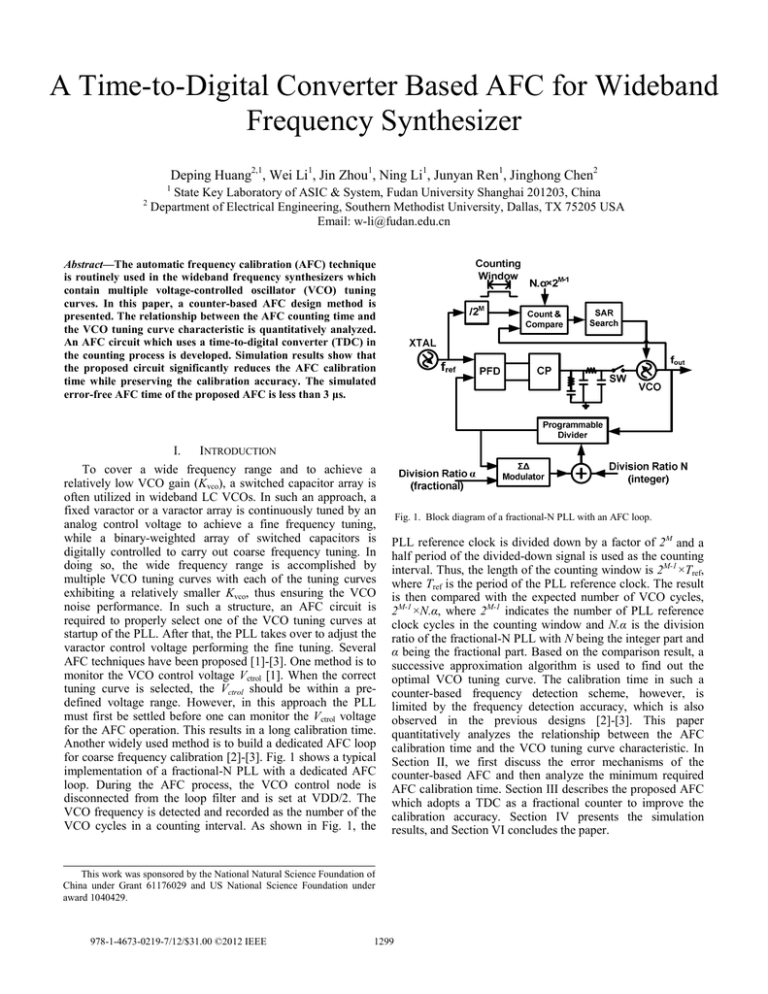
A Time-to-Digital Converter Based AFC for Wideband Frequency Synthesizer Deping Huang2,1, Wei Li1, Jin Zhou1, Ning Li1, Junyan Ren1, Jinghong Chen2 1 2 State Key Laboratory of ASIC & System, Fudan University Shanghai 201203, China Department of Electrical Engineering, Southern Methodist University, Dallas, TX 75205 USA Email: w-li@fudan.edu.cn Abstract—The automatic frequency calibration (AFC) technique is routinely used in the wideband frequency synthesizers which contain multiple voltage-controlled oscillator (VCO) tuning curves. In this paper, a counter-based AFC design method is presented. The relationship between the AFC counting time and the VCO tuning curve characteristic is quantitatively analyzed. An AFC circuit which uses a time-to-digital converter (TDC) in the counting process is developed. Simulation results show that the proposed circuit significantly reduces the AFC calibration time while preserving the calibration accuracy. The simulated error-free AFC time of the proposed AFC is less than 3 μs. I. INTRODUCTION To cover a wide frequency range and to achieve a relatively low VCO gain (Kvco), a switched capacitor array is often utilized in wideband LC VCOs. In such an approach, a fixed varactor or a varactor array is continuously tuned by an analog control voltage to achieve a fine frequency tuning, while a binary-weighted array of switched capacitors is digitally controlled to carry out coarse frequency tuning. In doing so, the wide frequency range is accomplished by multiple VCO tuning curves with each of the tuning curves exhibiting a relatively smaller Kvco, thus ensuring the VCO noise performance. In such a structure, an AFC circuit is required to properly select one of the VCO tuning curves at startup of the PLL. After that, the PLL takes over to adjust the varactor control voltage performing the fine tuning. Several AFC techniques have been proposed [1]-[3]. One method is to monitor the VCO control voltage Vctrol [1]. When the correct tuning curve is selected, the Vctrol should be within a predefined voltage range. However, in this approach the PLL must first be settled before one can monitor the Vctrol voltage for the AFC operation. This results in a long calibration time. Another widely used method is to build a dedicated AFC loop for coarse frequency calibration [2]-[3]. Fig. 1 shows a typical implementation of a fractional-N PLL with a dedicated AFC loop. During the AFC process, the VCO control node is disconnected from the loop filter and is set at VDD/2. The VCO frequency is detected and recorded as the number of the VCO cycles in a counting interval. As shown in Fig. 1, the Fig. 1. Block diagram of a fractional-N PLL with an AFC loop. PLL reference clock is divided down by a factor of 2M and a half period of the divided-down signal is used as the counting interval. Thus, the length of the counting window is 2M-1×Tref, where Tref is the period of the PLL reference clock. The result is then compared with the expected number of VCO cycles, 2M-1×N.α, where 2M-1 indicates the number of PLL reference clock cycles in the counting window and N.α is the division ratio of the fractional-N PLL with N being the integer part and α being the fractional part. Based on the comparison result, a successive approximation algorithm is used to find out the optimal VCO tuning curve. The calibration time in such a counter-based frequency detection scheme, however, is limited by the frequency detection accuracy, which is also observed in the previous designs [2]-[3]. This paper quantitatively analyzes the relationship between the AFC calibration time and the VCO tuning curve characteristic. In Section II, we first discuss the error mechanisms of the counter-based AFC and then analyze the minimum required AFC calibration time. Section III describes the proposed AFC which adopts a TDC as a fractional counter to improve the calibration accuracy. Section IV presents the simulation results, and Section VI concludes the paper. This work was sponsored by the National Natural Science Foundation of China under Grant 61176029 and US National Science Foundation under award 1040429. 978-1-4673-0219-7/12/$31.00 ©2012 IEEE 1299 (a) (a) (b) Fig. 2. (a) Counter-based frequency detection; (b) Frequency detection error. II. COUNTER-BASED AFC DESIGN ANALYSIS A. Frequency Detection Accuracy The frequency calibration accuracy of the AFC is mainly determined by the frequency detection accuracy which is based on cycle counting. As shown in Fig. 2(a), if there are N cycles of signal under detection in a given counting window TGATE, then the detected signal frequency fdetect is N/TGATE. However, due to the initial phase uncertainty, the jitter in the gating signal and the integer counter rounding effect, the counting result for a signal with a frequency fdetect can be round(fdetect·TGATE) ± 1 as indicated in Fig. 2(b), where the round function returns the closest integer to the argument. This causes a frequency detection error of ±1/TGATE, which is also the frequency resolution that the counter-based frequency detector can provide [3]. To reduce the error, long enough counting time is required, which unfortunately increases the synthesizer locking time. B. Minimum Counting Time Requirement Since the frequency detection accuracy of the AFC is limited by the width of the counting window TGATE, it is necessary to find out the minimum required counting time for a given VCO tuning curve characteristic. Besides the frequency detection error, the finite-precision numerical effect of the division ratio 2M-1×N.α also causes an incorrect AFC operation. Typically, only the integer part of 2M-1×N.α is treated as the expected number of VCO cycles. Thus, the worst-case numerical truncation error is 1/2M-1. In Fig. 3, curves A and B are two VCO tuning curves with fA and fB being their midpoint frequencies, respectively. During the AFC operation, fA and fB are detected and then compared with the target frequency fT. The curve with its midpoint frequency closer to the target frequency will be chosen. However, due to the frequency detection error and the division ratio truncation error, the AFC may select a wrong tuning curve. For example, if the target frequency fT is larger than the rightmost frequency of tuning curve B (the gray portion of curve A) and AFC chooses tuning curve B, then the (b) Fig. 3. Two worst-case scenarios causing incorrect AFC operation. PLL cannot be locked. Two worst-case scenarios of incorrect AFC operations are shown in Fig. 3. Fig. 3(a) depicts a scenario where the frequency detection error causes the detected frequencies to both exhibit a positive offset relative to their true value, i.e., the detected frequencies are fA′ and fB′, respectively; and the target frequency due to the division ratio truncation error is fT′. In this case, the AFC will mistakenly choose curve B if fT′ becomes closer to fB′ than fA′. Fig. 3(b) depicts another worst-case scenario where the detected frequency errors have opposite signs and there is no division ratio truncation error. Then, if fA′ and fB′ cross over the frequency (fA +fB)/2, the AFC will also mistakenly choose tuning curve B. To avoid these two situations, |fA′ − fT′| < |fB′ − fT′| should hold and thus the following two inequalities need to be satisfied. f step − 0.5 K vco ΔV + 2 / (2 M −1 Tref ) < 0.5 K vco ΔV − 2 / (2 M −1 Tref ) f step / 2 > 1/ (2M −1Tref ) (1) (2) In deriving the above inequalities, the frequency detection error of 1/TGATE=1/(2M-1Tref) as discussed in Section II.A is assumed. The worst-case frequency offset of fT due to the division ratio truncation error as discussed in II.A is also 1/(2M-1Tref). Eq. (1) ensures that fT′ is closer to fA′ than fB′ in Fig. 3(a) while (2) guarantees that fA′ and fB′ do not cross over the frequency point (fA +fB)/2 in Fig. 3(b). From (1) and (2), the minimum required counting window width can thus be derived as 1300 ⎧⎪ 4 2 ⎫⎪ 2 M −1 Tref = max ⎨ , (3) ⎬ ⎩⎪ K vco ΔV − f step f step ⎭⎪ Given a set of VCO tuning curves, (3) can be used to derive the required AFC counting time. For instance, assuming that fref = 40 MHz, KvcoΔV = 35 MHz, and the overlapping ratio of the tuning curves defined as 1−fstep/ (KvcoΔV) is 50% and thus the fstep is 17.5 MHz, then from (3), 2M-1 needs to be larger than 9.1. Since M is an integer, M = 5 is required, and thus the length of the counting window needs to be 2M-1×Tref = 16×Tref. III. N.a TDC Fractional Counter fvco Counter Fig. 4 shows the proposed AFC circuit that uses a TDC to detect the ratio between fvco and fref. There are two benefits of using TDC for the frequency detection. First, the frequency detection accuracy is increased because of the fractional period estimation. Secondly, since the detected frequency contains the fractional period information, the comparison in the AFC is no longer limited to the integer part of 2M-1×N.α. More fractional part of the division ratio can be included in the comparison, thus the target frequency offset caused by division ratio truncation is also reduced. These two improvements help to significantly reduce the AFC time while preserving the AFC accuracy. The TDC in this work shown in Fig. 4 adopts a configuration similar to that in [5], where an integer counter is used in conjunction with a fractional counter. The fractional counter implementation is shown in Fig. 5. The digital fractional phase is obtained by passing the VCO clock through a chain of inverters. In Fig. 5, the tr[n] is the time distance between each counting edge and the last VCO edge. It is normalized to the VCO period Tpvco. The Nfrac[n] is the residual fractional VCO period in the counting window. The smallest time interval Tres that can be resolved in the fractional counter is the TDC inverter delay. For a typical 130nm CMOS technology, it is about 30 ps. The counting resolution becomes Tres/Tvco, where Tvco is the VCO output period. Therefore, the frequency detection resolution and division ratio truncation error are both reduced to <<(M-1) + Ncntr 2M-1×N.a CMP fref=40MHz /2M e Final Word PROPOSED TDC-BASED AFC According to the above analysis, it can be found that the AFC frequency detection principle is quite similar to the Time-to-Digital Converter in an All Digital PLL (ADPLL) [4]. In the divider-less ADPLL, the TDC compares the DCO output signal with the reference signal by computing the number of DCO periods between two adjacent reference edges, i.e. the ratio between the output frequency and the reference frequency. This can be implemented by an integer counter, but the resolution is only equal to the DCO period which is too coarse for most applications. To improve the resolution, a fractional counter computing the residual time distance between the two reference edges after integer counting has been used [4]. The fractional counter measures the residual time distance between each reference edge and the last DCO edge before that using a multi-phase DCO output signal. This concept can be applied to the AFC design to reduce the counting error due to the initial phase uncertainty and the jitter of the VCO output. S Y N C State Machine Fig. 4. TDC-based AFC. Fig. 5. Fractional counter implementation in the TDC-based AFC. (Tres/Tvco)/(2M-1Tref). Eq. (3) for the TDC-based AFC can thus be modified as ⎧⎪ 4Tres / Tvco 2T / T ⎫⎪ 2 M −1 Tref = max ⎨ , res vco ⎬ (4) f step ⎭⎪ ⎪⎩ K vco ΔV − f step Assume that Tres = 30 ps and the VCO output frequency is 5 GHz, for the same set VCO tuning curves in Section II B, the minimum required 2M-1 is reduced to 1.4, which is much smaller than that of the conventional AFC method. It should be mentioned that the multi-phase counting requires more hardware and thus more power consumption than the conventional AFC approach. However, the AFC is only activated at the startup of the PLL; therefore, there is no power penalty during normal PLL operation. IV. SIMULATION RESULTS The conventional integer counter-based AFC and the TDC-based AFC have been designed in a 0.13 μm CMOS technology to verify the above analysis. A simulation setup shown in Fig. 6 is developed to find out the frequency searching behavior of these two circuits. Figs. 7 and 8 show the simulation results of the frequency calibration processes. The VCO outputs 64 discrete frequency bands ranging from 3.5 GHz to 5 GHz. The fstep is about 23.5 MHz. The reference clock frequency is 40 MHz. In the simulation, the calibration accuracies of the two AFCs are compared for a given counting time, which is set as 2×Tref. Fig. 7 shows the division ratio truncation effect on the frequency calibration process. The target frequency fT is 3778 MHz which is between two VCO output frequencies of 3761.8 MHz and 3785.6 MHz. The 3785.6 MHz tuning curve should be selected since it is closer 1301 9 4.3 x 10 Conventional AFC TDC-based AFC 4.2 Frequency(Hz) 4.1 Target Frequency: 3778MHz 4 3.9 3785.6MHz 3.8 3.7 Fig. 6. Simulation setup. 3761.8MHz 3.6 to the target frequency. However, because of the division ratio truncation error, the 3760 MHz is considered as the target frequency in the integer counter-based AFC. As a result, the AFC incorrectly chooses the 3761.8 MHz tuning curve. On the other hand, the TDC-based AFC correctly chooses the 3785.6 MHz tuning curve as it has a smaller division ratio truncation error. V. CONCLUSTION A counter-based AFC design analysis is presented in this paper. The minimum required counting time for a given set of VCO tuning curves is quantitatively derived. To the authors’ knowledge, this is the first time that such a quantitative analysis is developed. A TDC-based AFC method is proposed to improve the frequency detection accuracy and reduce the target frequency offset. The simulation results show that the TDC-based AFC is more robust than the conventional integer counter-based AFC method and greatly reduces the AFC time while preserving the frequency calibration accuracy. 0.5 1 1.5 Time(s) 2 2.5 3 -6 x 10 Fig. 7 Division ratio truncation effect on the AFC operation. 9 4.3 x 10 Conventional AFC TDC-based AFC 4.2 4.1 Frequency(Hz) Fig. 8 shows the initial phase uncertainty effect on the calibration process. A delay element is deliberately introduced to the VCO output in the simulation setup to adjust its phase. The target frequency is set at 4015.6 MHz. Simulation finds that when the delay ranges from 260 ps to 340 ps, the optimal tuning curve cannot be selected in the case of the conventional AFC scheme. This is because the 4023.6 MHz VCO output is detected as 4040 MHz under this initial phase condition in the conventional AFC method. This causes the AFC to mistakenly determine that the 3999.8 MHz tuning curve is closer to the target frequency. The TDC-based AFC, on the other hand, is less sensitive to the counting signal initial phase uncertainty due to its fractional phase estimation. Thus the frequency point is accurately detected and 4023.6MHz frequency is correctly identified to be closer to the target frequency. In summary, the simulation results show that the TDC-based AFC correctly chooses the optimal tuning curves with a 2×Tref counting window due to the improved frequency detection accuracy and the smaller target frequency offset. The conventional AFC, on the other hand, mistakenly selects the suboptimal tuning curves in both simulations because of the frequency detection error and the target frequency offset error. 3.5 0 4023.6MHz 4 3999.8MHz 3.9 3.8 Target Frequency: 4015.6MHz 3.7 3.6 3.5 0 0.5 1 1.5 2 2.5 Time(s) 3 -6 x 10 Fig. 8 Effect of initial phase uncertainty on the AFC operation. REFERENCES [1] [2] [3] [4] [5] 1302 T.-H. Lin and W. J. Kaiser, “A 900-MHz 2.5-mA CMOS frequency synthesizer with an automatic SC tuning loop,” IEEE J. Solid-State Circuits, vol. 36, no. 3, pp. 424–431, March 2001. H. Lee, J. Cho, K. Lee, I. Hwang, T. Ahn and K. Nah, et al, “A Σ-Δ fractional-N frequency synthesizer using a wide-band integrated VCO and a fast AFC technique for GSM/GPRS/WCDMA applications,” IEEE J. Solid-State Circuits, vol. 39, no. 7, pp. 1164–1169, July 2004. J. Shin and H. Shin, “A fast and high-precision VCO frequency calibration technique for wideband fractional-N frequency synthesizers,” IEEE Trans. Circuits and Systems I: Reg. Papers, vol. 57, no. 7, pp. 1573–1582, July 2010. E. Temporiti, C. Weltin-Wu, D. Baldi, R. Tonietto and F. Svelto, “A 3 GHz fractional all-digital PLL with a 1.8 MHz bandwidth implementing spur reduction techniques,” IEEE J. Solid-State Circuits, vol. 44, no. 3, pp. 824–834, March 2009. R. Staszewski, S. Vemulapalli, P. Vallur J. Wallberg and P. Balsara, “1.3 V 20 ps time-to-digital converter for frequency synthesis in 90-nm CMOS,” IEEE Trans. Circuits and Systems II: Express Briefs, vol. 53, no. 3, pp. 220–224, March 2006.
![Math 212, Fall 2011 Exam 1 Name: __________________________________ [24 points (6 pts each)]](http://s2.studylib.net/store/data/014903132_1-4c7abb595235e328bb226c37194c686a-300x300.png)


