GaN 70-100 GHz PA - HRL Laboratories
advertisement
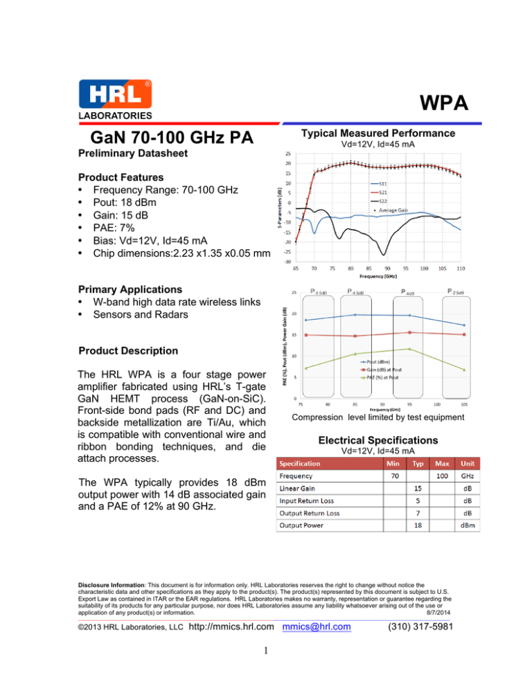
WPA Typical Measured Performance GaN 70-100 GHz PA Vd=12V, Id=45 mA Preliminary Datasheet Product Features • Frequency Range: 70-100 GHz • Pout: 18 dBm • Gain: 15 dB • PAE: 7% • Bias: Vd=12V, Id=45 mA • Chip dimensions:2.23 x1.35 x0.05 mm Primary Applications • W-band high data rate wireless links • Sensors and Radars Product Description The HRL WPA is a four stage power amplifier fabricated using HRL’s T-gate GaN HEMT process (GaN-on-SiC). Front-side bond pads (RF and DC) and backside metallization are Ti/Au, which is compatible with conventional wire and ribbon bonding techniques, and die attach processes. Compression level limited by test equipment Electrical Specifications Vd=12V, Id=45 mA The WPA typically provides 18 dBm output power with 14 dB associated gain and a PAE of 12% at 90 GHz. Disclosure Information: This document is for information only. HRL Laboratories reserves the right to change without notice the characteristic data and other specifications as they apply to the product(s). The product(s) represented by this document is subject to U.S. Export Law as contained in ITAR or the EAR regulations. HRL Laboratories makes no warranty, representation or guarantee regarding the suitability of its products for any particular purpose, nor does HRL Laboratories assume any liability whatsoever arising out of the use or application of any product(s) or information. 8/7/2014 ___________________________________________________________________________________________________________________________________________________________________________ ©2013 HRL Laboratories, LLC http://mmics.hrl.com mmics@hrl.com 1 (310) 317-5981 Absolute Maximum Ratings Outline Drawing CW Operation Parameter' Ra)ng' Unit' Input&Power&(Pin)& 10& dBm& Drain&Voltage&(Vd)& 12& V& <1&to&<3.5& V& Drain&Current&(Id)& 70& mA& Die&ACach&Temperature&(30&sec)& 290& °C& Gate&Voltage&Range&(Vg)& Exceeding any one or combination of the Absolute Maximum Ratings may result in permanent damage to the device. Application of Absolute Maximum Ratings on the device for an extended period of time may negatively affect the reliability of the device. DC Bond Pads are 0.09x0.075 mm; Bond pad locations shown from die etch to pad center. Caution: ESD sensitive device. Pout, PAE and Gain vs. Pin at 90 GHz Recommended Assembly Diagram Biasing Procedure Turn on 1) Vg = - 6 V 2) Vd = 12 V 3) Adjust Vg to obtain Id = 45 mA Turn off 1) Vd = 0V 2) Vg = 0V HRL recommends mounting the die on CuW heat spreader using AuSn eutectic solder. Disclosure Information: This document is for information only. HRL Laboratories reserves the right to change without notice the characteristic data and other specifications as they apply to the product(s). The product(s) represented by this document is subject to U.S. Export Law as contained in ITAR or the EAR regulations. HRL Laboratories makes no warranty, representation or guarantee regarding the suitability of its products for any particular purpose, nor does HRL Laboratories assume any liability whatsoever arising out of the use or application of any product(s) or information. 8/7/2014 ___________________________________________________________________________________________________________________________________________________________________________ ©2013 HRL Laboratories, LLC http://mmics.hrl.com mmics@hrl.com 2 (310) 317-5981
