400, du Parc, Saint-Eustache, Québec Canada, J7R 0A1
• Tel:
+1.450.491.5671
• +1.800.665.1166
• Fax: +1.450.491.3788
• www.heicolighting.com
Technical Bulletin #8
clipAledTM Signage Installation Guide
1.
Layout
2.
Loading
3.
Installation
INSTALLATION INSTRUCTIONS
1. Installation shall be done in accordance with the National Electrical Code (article 600) in the United States or the
Canadian Electrical Code (CSA22.1) in Canada. Also follow local electrical code ordinances when applicable.
2. The sign shall be built according to UL 48 and/or CSA C22.2 #207 and UL 879 and/or CSA C22.2 #207-M89 safety
standards.
3. Clean and remove all dust and debris from the inside of the channel. Keep the channel clean throughout the
installation.
4. The modules installed in the same sign should have the same bin letter. If not there might be small differences in
colors and this might make the completed sign look uneven. Further testing can be required.
5. Lay the bases inside the channel according to the provided layout. Use the provided double-sided tape.
6. Use #8 fasteners where necessary to hold the bases in place.
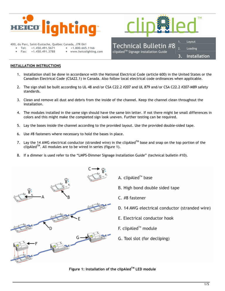
7. Lay the 14 AWG electrical conductor (stranded wire) in the clipAledTM base and snap on the top portion of the
clipAledTM. All modules are to be wired in series (figure 1).
8. If a dimmer is used refer to the “LMPS-Dimmer Signage Installation Guide” (technical bulletin #10).
Figure 1: Installation of the clipAledTM LED module
1/5
HEICO lightingTM Contactless LED System
clipAledTM Signage Installation Guide
VERIFICATION OF THE COMPLETED SIGN
1. The sign shall be tested for functionality, color rendering and illumination level before the on-site installation.
2. Test each letters individually to make sure the illumination is adequate. If applicable correct any seen problems.
3. Test the complete sign either as a whole or in sections. Verify that illumination is uniform throughout the sign.
INDOOR POWER SUPPLY ELECTRICAL CONNECTION
1. Installation shall be done in accordance to the applicable electrical code and specific application regulations.
2. A listed electrical enclosure approved for the purpose shall be used for the LMPS primary connection.
3. The Class 2 circuit shall be physically separated from other circuits types.
4. Use #8 fasteners to secure the power supply and the electrical box in place.
5. If more than one (1) LMPS is used, keep a spacing of at least one (1) inch (25.4 mm) between each LMPS.
6. If the Class 2 feeder circuit needs to be extended between the LMPS and the LED arrays, use twisted pair cable
type CL2 14 AWG or better, listed for the applicable environment (figure 2). Substitutions according to NEC table
725.154(G) and CEC article 16.210, 16-222, table 19 are permitted (also refer to CEC Appendix B).
Permitted substitutions for CL2 wires are: CMP, CL3P, CL2P, CMR, CL3R, CL2R, CMG, CM, PLTC, CL3.
7. For more details refer to the LMPS-350, LMPS DC-350, LMPS-750 product sheet (documents 11126.001 and
11978.000)
Figure 2: Electrical connection for indoor installation
(twisted pair extension and LMPS-350 shown, others are similar)
• IMPORTANT: The user is responsible for the safe electrical and mechanical installation of the power supply
and of the suitability of the wiring system, mounting surfaces and any mounting hardware used. Failure to
do so can lead to electrical and mechanical failure of the system and serious personal injury.
• The user is responsible for proper selection of the electrical conductor type that will be used for the specific
application.
• The Class 2 circuit shall be physically separated from other circuit types.
Specifications are subject to change without notice (Technical bulletin #8)
2/5
HEICO lightingTM Contactless LED System
clipAledTM Signage Installation Guide
OUTDOOR POWER SUPPLY ELECTRICAL CONNECTION
1. Installation shall be done in accordance to the applicable electrical code and specific application regulations.
2. A listed electrical enclosure approved for the purpose shall be used for the LMPS primary connection.
3. The power supply shall be oriented in a way that will not let condensing water accumulate in the enclosure.
4. In outdoor and/or damp environments the power supply shall be installed in an appropriate location and in a listed
electrical enclosure approved for the purpose (examples: NEMA 3, 3R, 3S, 3X, 3RX, 3SX or 4).
5. The Class 2 circuit shall be physically separated from other circuits types.
6. Use #8 fasteners to secure the power supply and the electrical box in place.
7. If more than one (1) LMPS is used, keep a spacing of at least one (1) inch (25.4 mm) between each LMPS.
8. If the Class 2 feeder circuit needs to be extended between the LMPS and the LED arrays, use twisted pair cable
type CL2 14 AWG or better, listed for the applicable environment (figure 2). Substitutions according to NEC table
725.154(G) and CEC article 16.210, 16-222, table 19 are permitted (also refer to CEC Appendix B).
Permitted substitutions for CL2 wires are: CMP, CL3P, CL2P, CMR, CL3R, CL2R, CMG, CM, PLTC, CL3.
9. For more details refer to the LMPS-350, LMPS DC-350, LMPS-750 product sheet (documents 11126.001 and
11978.000)
Figure 3: Electrical connection for outdoor installation
(twisted pair extension and LMPS-350 shown, others are similar)
• IMPORTANT: The user is responsible for the safe electrical and mechanical installation of the power supply
and of the suitability of the wiring system, mounting surfaces and any mounting hardware used. Failure to
do so can lead to electrical and mechanical failure of the system and serious personal injury.
• The user is responsible for proper selection of the electrical conductor type that will be used for the specific
application.
• The Class 2 circuit shall be physically separated from other circuit types.
Specifications are subject to change without notice (Technical bulletin #8)
3/5
clipAledTM Signage Installation Guide
HEICO lightingTM Contactless LED System
ON-SITE INSTALLATION
1. Turn off power before installation, inspection, repair or removal.
2. Use the appropriate extension wire where applicable.
3. Connect the channels to the power supplies according to the provided layout.
4. All channels shall be wired in series (figure 2).
5. Refer to technical bulletin #5 for troubleshooting details.
Figure 4: Typical installation
Specifications are subject to change without notice (Technical bulletin #8)
4/5
clipAledTM Signage Installation Guide
HEICO lightingTM Contactless LED System
DENSITY CONFIGURATIONS
The clipAledTM can be installed in many configurations to make for very high light density
Figure 5: Density configurations
Modules per foot
13
9
7
3
2
Table 1: Lumens per foot table
Lumens per foot
364
252
196
87
58
Watts per foot
6.50
4.05
3.15
1.50
1
• All technical data in this technical bulletin is based on test results and is believed to be correct. However since
the end use of HEICO lightingTM products, usage application and installation, is beyond our control, HEICO
lightingTM makes no warranty expressed or implied as to the fitness of use. Their use shall be solely by the
judgment and at the risk of the user notwithstanding any statement in this technical bulletin.
• The modules installed in the same sign should have the same bin letter.
• For other configurations and general information about layouts please contact HEICO lightingTM
• Refer to the product sheet for more information about the
LMPS-350, LMPS DC-350, LMPS-750 power supplies and the clipAledTM modules.
© HEICO lighting™, 2012 – All rights reserved. Made in Canada.
For customer service, call 1.800.665.1166
Specifications are subject to change without notice (Technical bulletin #8)
5/5


