LED Traffic Signal Modules Incandescent Look IL Series (Type 1
advertisement

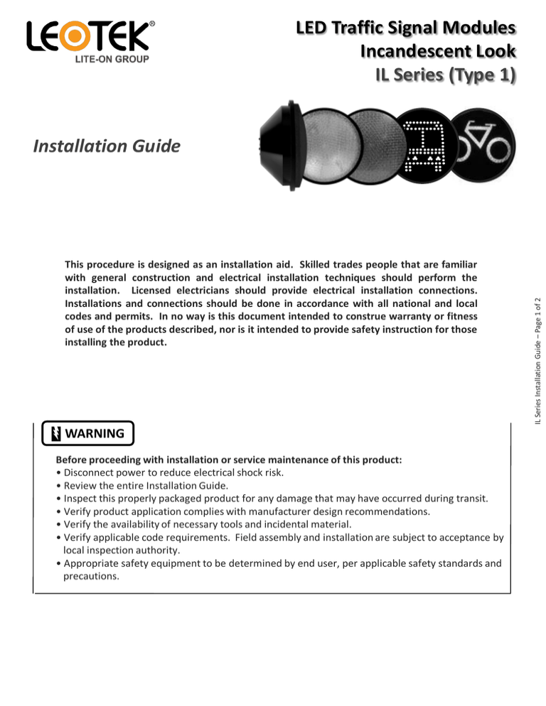
LED Traffic Signal Modules Incandescent Look IL Series (Type 1) This procedure is designed as an installation aid. Skilled trades people that are familiar with general construction and electrical installation techniques should perform the installation. Licensed electricians should provide electrical installation connections. Installations and connections should be done in accordance with all national and local codes and permits. In no way is this document intended to construe warranty or fitness of use of the products described, nor is it intended to provide safety instruction for those installing the product. WARNING Before proceeding with installation or service maintenance of this product: • Disconnect power to reduce electrical shock risk. • Review the entire Installation Guide. • Inspect this properly packaged product for any damage that may have occurred during transit. • Verify product application complies with manufacturer design recommendations. • Verify the availability of necessary tools and incidental material. • Verify applicable code requirements. Field assembly and installation are subject to acceptance by local inspection authority. • Appropriate safety equipment to be determined by end user, per applicable safety standards and precautions. IL Series Installation Guide – Page 1 of 2 Installation Guide E B G F A D H A Wing Nuts E Existing Lens B Front Panel F Socket and Reflector C G Module Screws D Metal Plates H Spade Terminal Step 1 - Loosen the two wing-nuts A located on the front panel B and then open the front panel. Step 2 - Loosen the four screws C on the back side of the front panel and turn the four metal plates D to remove the existing lens E . Step 3 - Unscrew the existing incandescent light bulb from the socket (caution: light bulb may be hot) and remove the reflector F . Step 4 - Remove the protective film from the lens of the module. Step 5 - Mount the module G to the front panel. Use the existing metal plates D and screws C to mount the module. For balls, make sure the “TOP” arrow is pointing upward. Step 6 - Securely connect the spade terminal H to the traffic signal power terminals, which are connected to the controller. LED modules have colored wire: red, yellow, and brown wires for phase conductor, and white wire for neutral line. Step 7 - Close the panel and tighten the two wing nuts. Step 8 - If the external flexible cable or cord of this module is damaged, it shall be replaced by a special cord or cord exclusively available from the manufacturer or service agent. Terminal block not included. Please visit Leotek Electronics USA Corp. at www.leotek.com V8-071713 | Information provided subject to change without notice. IL Series Installation Guide – Page 2 of 2 C


