AC circuits - Rice Space Institute
advertisement

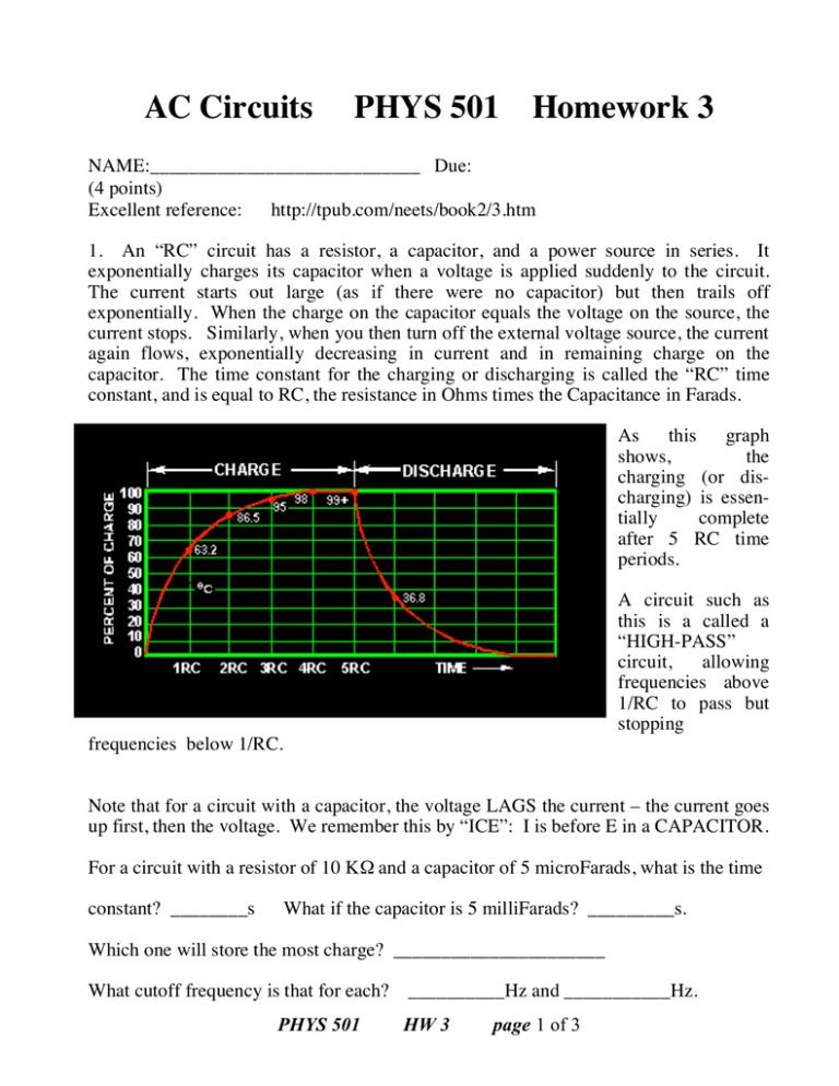
AC Circuits PHYS 501 Homework 3 NAME:____________________________ Due: (4 points) Excellent reference: http://tpub.com/neets/book2/3.htm 1. An “RC” circuit has a resistor, a capacitor, and a power source in series. It exponentially charges its capacitor when a voltage is applied suddenly to the circuit. The current starts out large (as if there were no capacitor) but then trails off exponentially. When the charge on the capacitor equals the voltage on the source, the current stops. Similarly, when you then turn off the external voltage source, the current again flows, exponentially decreasing in current and in remaining charge on the capacitor. The time constant for the charging or discharging is called the “RC” time constant, and is equal to RC, the resistance in Ohms times the Capacitance in Farads. As this graph shows, the charging (or discharging) is essentially complete after 5 RC time periods. A circuit such as this is a called a “HIGH-PASS” circuit, allowing frequencies above 1/RC to pass but stopping frequencies below 1/RC. Note that for a circuit with a capacitor, the voltage LAGS the current – the current goes up first, then the voltage. We remember this by “ICE”: I is before E in a CAPACITOR. For a circuit with a resistor of 10 KΩ and a capacitor of 5 microFarads, what is the time constant? ________s What if the capacitor is 5 milliFarads? _________s. Which one will store the most charge? ______________________ What cutoff frequency is that for each? __________Hz and ___________Hz. PHYS 501 HW 3 page 1 of 3 2. What is the total capacitance of a 5 mF and a 10 mF capacitor in parallel? ___________ in series? _______________________ Note: the equation for Capacitance in series and parallel is different from that of Resistance. Only with capacitors in PARALLEL does each one get the full voltage. Therefore only there is the total Capacitance equal to the sum of the pieces: C parallel = C1 + C2 + C3. If you have capacitors in series, they have to share the voltage and the net capacitance is less: (a similar equation to that of resistors in parallel) C series = 1 / (1/C1 + 1/C2 + 1/C3) . Good reference: http://tpub.com/neets/book2/4.htm 3. An inductor is similar, except that the Voltage leads the Current. “ELI”: E is before I in an L-circuit. The time constant for an inductive circuit (with a voltage, a resistor, and an inductor) is L/R, where R is the resistance in Ohms and L is the inductance in Henrys. Capacitors and Inductors are said to have "Reactance" – like resistance but out of phase. The reactance of a Capacitor is XC = 1/2πfC (often written as negative) The reactance of an Inductor is XL = 2πfL (C is measured in Farads, L in Henrys, f in Hz) What is the total inductance of a 2 Henry PHYS 501 HW 3 page 2 of 3 and 5 Henry inductor in series? ________ In Parallel?_______________ Note: the equation for Inductors in series and parallel is similar that of Resistance. If you have inductors in series, you just add up the inductance: L series = L1 + L2 + L3. If you have inductors in parallel, the net inductance is less: (a similar equation to that of resistors in parallel) L parallel = 1 / (1/L1 + 1/L2 + 1/L3) 4. An “LC” circuit has a resistor, inductor, and capacitor in series. This is a “tuned” circuit, that has minimum reactance at a specific frequency. First the capacitor builds up energy in charge and then the inductor builds up energy in magnetic field. The total Reactance is |XC - XL. | The net is always shown as positive, and if the inductive is larger, the net is inductive; if the capacitative is larger, the net is capacitative. So to make that minimum, you want XC = XL so, (2πf)2 = 1/LC So f = 1 / (2π (sqrt (LC) ) If you drive the circuit exactly at it resonant frequency, it will "ring" with minimum loss. Now, for a cheapie AM radio, we want to tune for 740KHz. If the capacitor is 1 microFarad, what would the effective inductance of the coil be? (note: It's actually 120 pF in the radio we will be making) (show your work!) PHYS 501 HW 3 page 3 of 3


