2 - 3B Scientific
advertisement

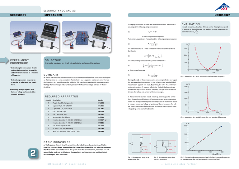
E l e c t r i c i t y / D C a n d AC UE3050321 Impedances UE3050321 To simplify calculations for series and parallel connections, inductances L are assigned the following complex reactance: XL = i ⋅2π ⋅ f ⋅L (1) E VAL U ATION For each frequency f, the phase shift φ as well as the amplitudes I0 and U0 are read on the oscilloscope. The readings are used to calculate the U total impedance:Z 0 = 0 . I0 f: Alternating current’s frequency Furthermore, capacitances C are assigned the following complex reactance: XC = (2) 1 i ⋅2π ⋅ f ⋅C ZS / The total impedance of a series connection without an ohmic resistance therefore is: 1 ⎞ ⎛ ZS = i ⋅ ⎜ 2π ⋅ f ⋅L − , ⎝ 2π ⋅ f ⋅C ⎟⎠ (3) E X P E RIME NT PROC E DURE OB JE CTI V E • Determining resonant frequency as a function of inductance and capacitance. • Observing changes in phase shift between voltage and current at the resonant frequency. 1000 1 1 ⎛ ⎞ = −i ⋅ ⎜ − 2 ⋅ π ⋅ f ⋅C ⎟ ⎝ 2 ⋅ π ⋅ f ⋅L ⎠ ZP (4) • Determining the impedances of series and parallel connections of capacitive and inductive reactances as a function of frequency. 2000 The corresponding calculation for a parallel connection is: Determining impedance in a circuit with an inductive and a capacitive reactance 3000 0 At the resonant frequency S UMM ARY AC circuits with inductive and capacitive reactances show resonant behaviour. At the resonant frequency, the impedance of a series connection of an inductive and a capacitive reactance is zero, whereas the impedance of a parallel connection is infinite. This experiment examines this phenomenon with the help of an oscilloscope and a function generator which supplies voltages between 50 Hz and 20,000 Hz. Re quired A p pa r at us Quantity Description fr = (5) Number 1 Plug-In Board for Components 1012902 1 Capacitor 1 µF, 100 V, P2W19 1012955 1 Capacitor 4.7 µF, 63 V, P2W19 1012946 1 Coil S with 600 Taps 1001000 1 Coil S with 1200 Taps 1001002 1 Resistor 10 Ω, 2 W, P2W19 1012904 1 Function Generator FG 100 (230 V, 50/60 Hz) 1009957or Function Generator FG 100 (115 V, 50/60 Hz) 1009956 1 USB Oscilloscope 2x50 MHz 1017264 2 HF Patch Cord, BNC/4 mm Plug 1002748 1 Set of 15 Experiment Leads, 75 cm 1 mm² 1002840 1 2 ⋅ π ⋅ L⋅C 10 100 1000 f / Hz 10000 Fig. 3: Impedance of a series connection as a function of frequency the impedance Zs of the series connection comprising inductive and capacitive reactances therefore vanishes, i.e. the voltages across both individual reactances are opposite and equal. By contrast, the value of a parallel connection’s impedance ZP becomes infinite, i.e. the individual currents are opposite and equal. At the resonant frequency, the sign of the phase shift between the voltage and current furthermore changes. In the experiment, resonant circuits are set up as series / parallel connections of capacitors and inductors. A function generator serves as a voltage source with an adjustable frequency and amplitude. An oscilloscope is used to measure current and voltage as functions of the set frequency. The voltage U and current I are displayed on the oscilloscope; I corresponds to the voltage drop across a small load resistor. ZP / 2000 1500 1000 500 0 10 100 1000 10000 f / Hz Fig. 4: Impedance of a parallel connection as a function of frequency f / Hz 1500 1000 C b a s ic PRINCIPL E S 2 As the frequency of an AC circuit’s current rises, the inductive reactance rises too, while the capacitive reactance drops. Series and parallel connections of capacitive and inductive reactances therefore exhibit resonant behaviour. One speaks here of a resonant circuit, its current and voltage oscillating back and forth between the capacitance and inductance. An additional ohmic resistor dampens these oscillations. U(t) L L Rm I(t)·Rm 500 C U(t) U(t) Rm I(t)·Rm 0 0 500 1000 1500 1/ 2 LC / Hz Fig. 1: Measurement setup for a series connection 3B Scientific® Experiments U(t) Fig. 2: Measurement setup for a parallel connection Fig. 5: Comparison between measured and calculated resonant frequencies for a series connection (red) and a parallel connection (blue) ...going one step further


