sDAS Remote Access Unit
advertisement
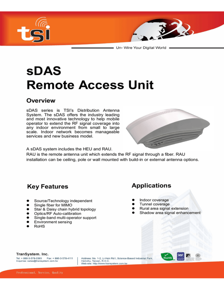
sDAS Remote Access Unit Overview sDAS series is TSI’s Distribution Antenna System. The sDAS offers the industry leading and most innovative technology to help mobile operator to extend the RF signal coverage into any indoor environment from small to large scale. Indoor network becomes manageable services and new business model. A sDAS system includes the HEU and RAU. RAU is the remote antenna unit which extends the RF signal through a fiber. RAU installation can be ceiling, pole or wall mounted with build-in or external antenna options. Key Features Applications Source/Technology independent Single fiber for MIMO Star & Daisy chain hybrid topology Optics/RF Auto-calibration Single-band multi-operator support Environment sensing RoHS Indoor coverage Tunnel coverage Rural area signal extension Shadow area signal enhancement Specification RAU Radio Interface Frequency Range Omni Antenna Gain Panel Antenna Gain NC type (optional) Downlink Output Power Refer to Table RAU 4dBi frequency > 1700MHz, 0dBi frequency < 1000MHz 9dBi *only available for frequency > 1700MHz N type (F) connector x 2 FDD : +12 ~ +18 dBm per port, 1dB/step. +18 dBm per port power supports 64QAM 5/6 OFDM at 4% EVM TDD : +14 ~ +20dBm per port, 1dB/step. +20 dBm per port power supports 64QAM 5/6 OFDM at 4% EVM Fiber Interface Power Supply Environmental Dimensions & Weight Mounting RAU LED PWR Fiber Uplink Noise Figure Fiber Connector Built-in Optical Tapper Wavelength Allocation Laser O/P Power Optical RX Sensitivity Power input DC Input Range Power Consumption Operating Temp Range Dimensions Weight Color Green Red Green Flash Green Dark 6dB max. at max. UL gain SC/APC x 2 Tapped 20%, Through 80% Downlink : 1550nm , Uplink : 1310nm -1dBm typical, -2.5dBm minimum -2dBm 802.3at – B type Compatible +36 ~ +58 VDC 20W Max. 0 ~ +45 ℃ 230 (L) x 142 (W) x 80 (H) mm 1.4 Kg Wall Mount or Pole Mount Description Power on RAU system DC abnormal RAU has been provisioned and calibrated RAU has been provisioned but is standby for calibration or under diagnostic test or firmware upgrade Low optical power System Function and Features Initialization and Configuration RF Power & Frequency Normal Operation Mode Uplink Path Gain RAU Link Parameter Monitoring RAU Serial Number Fiber Connection Loss Downlink Path Diagnosis & Calibration Uplink Path Calibration HEU Link Parameter Monitoring Environment Sensing Certification Based on BTS input power level set optimal HEU RF operating point S/N display on GUI after RAU topology set Display on GUI after RAU topology set RAU output power default: +18dBm per port, +21dBm total Default: 0dB gain from RAU antenna port to HEU RF port -15 ~ +15 dB, 1dB/step. Default : 0dB Downlink output power : aggregated total power Uplink RSSI:15MHz bandwidth for each selectable channel, center frequency 5 MHz/step Fiber loss display RF1/RF2, D/L input power level from BS,15MHz bandwidth for each selectable channel, center frequency 5 MHz/step Uplink CE/FCC Table RAU Band Duplex Mode Frequency Uplink Downlink Uplink Downlink Uplink Downlink Uplink Downlink Uplink Downlink Uplink Downlink 1920 ~ 1980MHz 2110 ~ 2170MHz 1850 ~ 1910MHz 1930 ~ 1990MHz 1710 ~ 1785MHz 1805 ~ 1880MHz 1710 ~ 1755MHz 2110 ~ 2155MHz 704 ~ 716MHz 734 ~ 746MHz 703 ~ 748MHz 758 ~ 803MHz 1 FDD 2 FDD 3 FDD 4 FDD 17 FDD 28 FDD 40 TDD 2300 ~ 2400MHz 41 TDD 2496 ~ 2690MHz Model No. / Option RAU-01_01 OA, PA, NC RAU-02_01 OA, PA, NC RAU-03_01 OA, PA, NC RAU-04_01 OA, PA, NC RAU-17_01 OA, NC RAU-28_01 OA, NC RAU-40_01 OA, PA, NC RAU-41_01 OA, PA, NC OA : OMNI antenna , PA : Panel antenna, NC : N-type connector Specifications are subject to change without prior notice.
