Weighted Sum Rate Optimization for Downlink Multiuser
advertisement
Weighted Sum Rate Optimization for Downlink
Multiuser MIMO Systems with per Antenna Power
Constraint: Downlink-Uplink Duality Approach
arXiv:1311.6440v1 [math.OC] 25 Nov 2013
Tadilo Endeshaw Bogale and Luc Vandendorpe, Email: {tadilo.bogale, luc.vandendorpe}@uclouvain.be
ICTEAM Institute, Universitè catholique de Louvain, Place du Levant B-1348, Louvain La Neuve, Belgium
Abstract— This paper considers weighted sum rate maximization constrained with a per base station (BS) antenna power
problem for multiuser multiple-input multiple-output (MIMO)
systems. For this problem, we propose new downlink-uplink
duality based solution. We solve the problem as follows. First, by
introducing additional optimization variables, we reformulate our
problem into an equivalent problem that incorporates a weighted
sum mean-square-error (MSE) term. Second, we establish novel
weighted sum MSE duality. The duality is established by modifying the input covariance matrix of the dual uplink problem, and
formulating the noise covariance matrix of the uplink channel
as a fixed point function. Third, we optimize the introduced
variables and powers in the downlink channel by a Geometric
Program (GP) method. Fourth, using the duality result and the
solution of GP, we apply alternating optimization technique to
solve the original downlink problem. In our simulation results,
we have observed that the proposed duality based solution utilizes
less power than that of existing algorithms.
I. I NTRODUCTION
Multiple-input multiple-output (MIMO) system is a
promising approach to fully exploit the spectral efficiency of
wireless channels. The capacity region of a MIMO broadcast
channel is achieved by dirty paper coding (DPC) technique of
[1]. However, since DPC is non-linear, practical realization of
DPC is difficult. Due to this, linear processing is motivated as
it exhibits good performance/complexity trade-off.
In [2] and [3], weighted sum rate maximization constrained
with a per-BS antenna power problem has been examined.
Furthermore, simulation results demonstrate that the approach
of the latter paper has better achievable weighted sum rate
than that of [2]. Both of these papers examine their problems
directly in the downlink channel. In the downlink channel,
since the precoders of all users are jointly coupled, downlink
transceiver design problems have more complicated mathematical structure than that of the dual uplink problems [4], [5].
In [6], we have demonstrated that for a per BS antenna power
constrained sum MSE-based problems, the duality approach
of [6] requires less total BS power than the approach of [7].
Due to these reasons, duality approach for solving downlink
problems has received a lot of attention.
In this paper, we examine the weighted sum rate maximization constrained with a per-BS antenna power problem (P1). For this problem, we propose new duality based
The authors would like to thank the Region Wallonne for the financial
support of the project MIMOCOM in the framework of which this work has
been achieved.
n1
HH
1
d1
d2
=d
B
n2
W1H
W2H
HH
2
nK
dK
HH
K
H
WK
(a)
Fig. 1.
b1
d
b2
d
bK
d
d1
V1
H1
d2
V2
H2
dK
VK
HK
n
TH
b
d
(b)
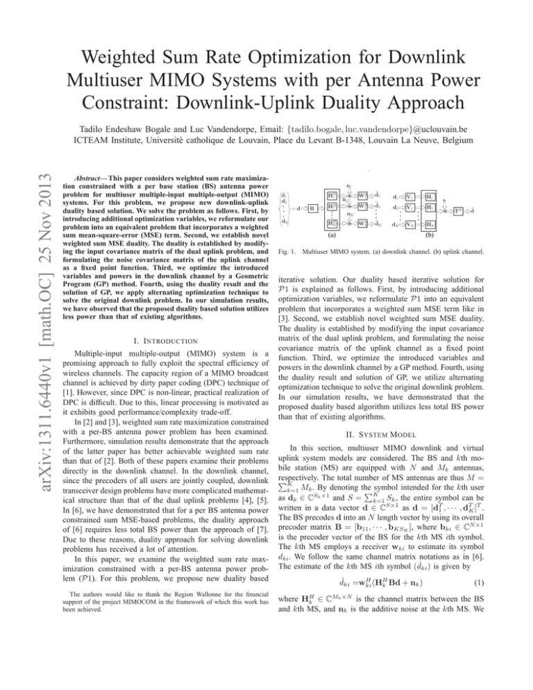
Multiuser MIMO system. (a) downlink channel. (b) uplink channel.
iterative solution. Our duality based iterative solution for
P1 is explained as follows. First, by introducing additional
optimization variables, we reformulate P1 into an equivalent
problem that incorporates a weighted sum MSE term like in
[3]. Second, we establish novel weighted sum MSE duality.
The duality is established by modifying the input covariance
matrix of the dual uplink problem, and formulating the noise
covariance matrix of the uplink channel as a fixed point
function. Third, we optimize the introduced variables and
powers in the downlink channel by a GP method. Fourth, using
the duality result and solution of GP, we utilize alternating
optimization technique to solve the original downlink problem.
In our simulation results, we have demonstrated that the
proposed duality based algorithm utilizes less total BS power
than that of existing algorithms.
II. S YSTEM M ODEL
In this section, multiuser MIMO downlink and virtual
uplink system models are considered. The BS and kth mobile station (MS) are equipped with N and Mk antennas,
respectively.
The total number of MS antennas are thus M =
PK
M
.
By
denoting the symbol intended for the kth user
k
k=1
PK
as dk ∈ CSk ×1 and S = k=1 Sk , the entire symbol can be
written in a data vector d ∈ CS×1 as d = [dT1 , · · · , dTK ]T .
The BS precodes d into an N length vector by using its overall
precoder matrix B = [b11 , · · · , bKSK ], where bki ∈ CN ×1
is the precoder vector of the BS for the kth MS ith symbol.
The kth MS employs a receiver wki to estimate its symbol
dki . We follow the same channel matrix notations as in [6].
The estimate of the kth MS ith symbol (dˆki ) is given by
H
dˆki =wki
(HH
k Bd + nk )
(1)
where
∈C
is the channel matrix between the BS
and kth MS, and nk is the additive noise at the kth MS. We
HH
k
Mk ×N
assume that the entries of dk are i.i.d zero-mean circularly
symmetric complex Gaussian (ZMCSCG) random variables
H
all with unit variance, i.e., E{dk dH
k } = ISk , E{dk di } = 0,
∀i 6= k, and E{dk nH
}
=
0.
And
n
is
a
ZMCSCG
random
k
i
variable with covariance matrix Rnk ∈ CMk ×Mk .
To establish our new weighted sum MSE duality (for
solving P1), we model the virtual uplink channel system
model as shown in Fig. 1.(b). This channel is modeled by
introducing precoders {Vk = [vk1 , · · · , vkSk ]}K
k=1 and decoders {Tk = [tk1 , · · · , tkSk ]}K
,
where
v
∈
CMk ×1 and
ki
k=1
N ×1
tki ∈ C
, ∀k, i. It is assumed that the kth user ith symbol
(dki ) is an i.i.d ZMCSCG random variable with variance ζki ,
H
i.e., E{dki dH
ki } = ζki , E{dki djm } = 0, ∀(j, m) 6= (k, i), and
}
=
0.
Moreover,
n
is
a ZMCSCG random variable
E{dk nH
i
with diagonal covariance matrix Ψ = diag(ψ1 , · · · , ψN ).
For the downlink system model of Fig. 1.a, the MSE
between dki and dˆki can be expressed as
ξki = Ed {(dˆki − dki )(dˆki − dki )H }
=
H
H
wki
(HH
k BB Hk
+ Rnk )wki −
(2)
H H
2ℜ{wki
Hk bki }
+ 1.
MSE from downlink to uplink and vice versa by using only
one scaling factor1 . Then, we employ the technique of [6] to
ensure the power constraint of each BS antenna at step (4).
Algorithm I
Initialization: Set {Bk }K
k=1 such that [BB]n,n = pn , ∀n.
Update {Wk }K
using
MMSE receiver approach, i.e.,
k=1
H
−1 H
Wk = (HH
Hk Bk , ∀k.
k BB Hk + Rnk )
Update {τki , νki , ∀i}K
k=1 by solving
min
{τki ,νki ,∀i}K
k=1
Sk
K Y
Y
k=1 i=1
(3)
Mathematically, the weighted sum rate maximization problem can be formulated as
P1 : max
{B}
Sk
K X
X
k=1 i=1
(4)
˜
where Rki = log2 (ξ˜ki )−1 and ωki ≥ 0 are the achievable
rate [3], [4] and weighting factor of the kth user ith symbol,
respectively, and p̆n is the maximum available power at the
nth BS antenna. Without loss of generality, we assume that
{0 < ωki < 1, ∀i}K
k=1 . After several steps, the above problem
can be equivalently formulated as [3] (see (16) of [3])
min
{τki ,νki ,bki ,wki ,∀i}K
k=1
Sk
K X
X
K
θki
k=1 i=1
Sk
K Y
Y
s.t [BBH ]n,n ≤ p̆n ,
µki
τki
,
2)
4)
5)
ωki Rki , s.t [BBH ]n,n ≤ p̆n , ∀n
S
k
1 γki X X
ηki ξki ,
νki +
τki
i=1
k=1 i=1
k
1 γki X X
˜
ηki ξ˜ki ,
νki +
τki
i=1
k=1
νki = 1, νki > 0, τki > 0 ∀k, i.
(7)
DL
ξw
= tr{η[WH ΓDL W − 2ℜ{WH HH B} + I]} (8)
3)
III. P ROBLEM F ORMULATION
S
K
θki
Repeat
1) By the current {Bk , Wk }K
the downlink
k=1 , compute
P K PS k
DL
DL
= k=1 i=1
weighted sum MSE (i.e., ξw
ηki ξki
).
When perfect CSI is available at the BS and MSs, the
minimum MSE (MMSE) receiver of the kth user ith symbol
H
−1 H
is given as wki = (HH
Hk bki . Plugging
k BB Hk + Rnk )
wki into (2), we get the MMSE of the kth user ith symbol as
˜
H
H
−1 H
ξ˜ki = 1 − bH
Hk bki .
ki Hk (Hk BB Hk + Rnk )
Sk
K X
X
(6)
where H = [H1 , · · · , HK ], W = blkdiag(Wk , ∀k),
η = diag(ηki , ∀k, i), Rn = blkdiag(Rnk , ∀k) and
ΓDL = HH BBH H + Rn .
Uplink channel
Transfer the total weighted sum MSE from downlink to
uplink channel.
Update {Tk }K
k=1 using MMSE receiver technique.
Downlink channel
Transfer the total weighted sum MSE from uplink to
downlink channel.
K
Update {Wk }K
k=1 by (6) and {τki , νki , ∀i}k=1 by (7).
Until convergence.
IV. W EIGHTED SUM MSE DOWNLINK - UPLINK DUALITY
To establish this duality, we first compute the total
weighted sum MSE in the uplink channel as
UL
ξw
= tr{λ(TH ΣT − 2ℜ{ζTH HV} + ζ)}
diag({ζki , ∀i}K
k=1 ),
H
(9)
diag({λki , ∀i}K
k=1 ),
where ζ =
λ=
Σ=
HVζVH H + Ψ, V = blkdiag(V1 , · · · , VK ) and T =
[T1 , · · · , TK ] with λki as the MSE weight of the kth user ith
symbol. When ζ = λ = I, (9) turns to (5) of [6].
k=1
νki = 1, νki > 0, τki > 0 (5)
k=1 i=1
1
1−ωki ,
1
ωki
µki =
− 1 and θki =
where ηki =
γki =
(1−ωki )
K
ωki µki
. For fixed {τki , νki , ∀i}k=1 , the above optimization problem has the same mathematical structure as that of the
downlink weighted sum MSE minimization problem. ThereK
fore, by keeping {τki , νki , ∀i}K
k=1 constant, {bki , wki , ∀i}k=1
can be optimized by applying MSE downlink-uplink duality
technique. For better exposition, let us summarize our duality
based approach for solving P1 as shown in Algorithm I.
In the following, we first establish our new weighted sum
MSE downlink-uplink duality (i.e., to perform steps (2) and
(4)). The current duality is able to transfer the weighted sum
A. Weighted sum MSE transfer (From downlink to uplink)
To apply this weighted sum MSE transfer for P1, we set
the uplink precoder, decoder, input variance and weights as
V = W, T = B, ζ = η, λ = I.
Substituting (10) into (9) and equating
τ̃ =
N
X
DL
ξw
ψn p̃n = p̃T ψ
=
UL
ξw
(10)
gives
(11)
n=1
1 Note that for a total BS power constrained MSE-based problems, the
approaches of [5] and [8] compute S scaling factors to transfer the weighted
sum MSE from uplink to downlink channel and vice versa. This computation
requires O(S 3 ) operations (see [5] and [8] for more details). Thus, the current
duality is more computational efficient than that of the existing duality.
PK
where τ̃ = k=1 tr{η k WkH Rnk Wk }, ψ = [ψ1 , · · · , ψN ]T ,
¯H
¯ ¯
p̃ = [p̃1 , · · · , p̃N ]T , p̃n = tr{b̃H
n b̃n } and b̃n is the nth row of
B. The above equation shows that by choosing any {ψn }N
n=1
that satisfy (11), one can transfer the precoder/decoder pairs of
the downlink channel to the corresponding decoder/precoder
U L2
DL
U L2
, where ξw
pairs of the uplink channel ensuring ξw
= ξw
is the uplink weighted sum MSE at step 2 of Algorithm I.
However, here {ψn }N
n=1 should be selected in a way that P1
can be solved by Algorithm I. To this end, we choose ψ as
τ̃ ≥ p̃T ψ.
(12)
By doing so, the uplink channel weighted sum MSE is less
DL
than the downlink channel weighted sum MSE (i.e., ξw
≥
U L2
ξw ). As will be clear later, to solve (5) with Algorithm I,
ψ should be selected as in (12). This shows that step 2 of
Algorithm I can be carried out with (10).
To perform step 3 of Algorithm I, we update T of (10)
by using the uplink MMSE receiver which is expressed as
T =Σ−1 HVζ = (HWηWH HH + Ψ)−1 HWη
(13)
where the second equality is obtained from (10) (i.e., V=W
and ζ = η). The above expression shows that by choosing
H H
−1
exists.
{ψn > 0}N
n=1 , we ensure that (HWηW H + Ψ)
Next, we transfer the total weighted sum MSE from uplink
to downlink channel (i.e., we perform step 4 of Algorithm
I) and show that the latter MSE transfer ensures the power
constraint of each BS antenna.
B. Weighted sum MSE transfer (From uplink to downlink)
For a given total weighted sum MSE in the uplink channel
with ζ = η and λ = I, we can achieve the same weighted
sum MSE in the downlink channel (with the MSE weighting
matrix η) by using a nonzero scaling factor (β) which satisfies
e = βT, W
f = V/β.
B
(14)
In this precoder/decoder transformation, we use the notations
e and W
f to differentiate with the precoder and decoder
B
DL
matrices used in Section IV-A. By substituting (14) into ξw
e
f
(with B=B, W=W) and then equating the resulting sum MSE
with that of the uplink channel (9), β can be determined as
β 2 = PN
n=1
τ̃
ψn t̃H
n t̃n
(15)
where t̃H
n is the nth row of the MMSE matrix T (13).
The power of each BS antenna in the downlink channel is
thus given by
τ̃ t̃H
n t̃n
2 H
e
eH b
≤ p̆n , ∀n
b
n n =tr{β t̃n t̃n } = PN
H
i=1 ψi t̃i t̃i
(16)
e H is the nth row of B.
e By multiplying both sides
where b
n
of (16) by ψn , we can rewrite the above expression as ψn ≥
ψ t̃H t̃
fn , ∀n, where fn = p̆τ̃n PN n ψn t̃nH t̃ . Now, suppose that there
i=1 i i i
exist {ψn > 0}N
n=1 that satisfy
ψn = fn , ∀n.
(17)
From (17), we get ψn p̆n = fn p̆n , ∀n. It follows that
N
X
ψn p̆n =
N
X
fn p̆n = τ̃ .
(18)
n=1
n=1
The above expression shows that the solution of (17) satisfies
(18). Moreover, as {p̆n ≥ p̃n }N
n=1 , the latter solution also satisfies (12). Therefore, for problem P1, by choosing {ψn }N
n=1
such that (17) is satisfied, step 4 can be performed.
Next, we show that there exists at least a set of feasible
{ψn > 0}N
n=1 that satisfy (17). In this regard, we consider the
following Theorem [9].
Theorem 1: Let (X, k.k2 ) be a complete metric space. We
say that ̥ : X → X is an almost contraction, if there exist
κ ∈ [0, 1) and χ ≥ 0 such that
k̥(x) − ̥(y)k2 ≤ κkx − yk2 + χky − ̥(x)k2 ,
∀x, y ∈ X.
(19)
If ̥ satisfies (19), then the following holds true.
1) ∃x ∈ X : x = ̥(x).
2) For any initial x0 ∈ X, the iteration xn+1 = ̥(xn )
for n = 0, 1, 2, · · · converges to some x⋆ ∈ X.
3) The solution x⋆ is not necessarily unique.
Proof: See Theorem 1.1 of [9].
By defining ̥ as
PN̥(ψ) , [f1 , f2 , · · · , fN ] with {ψn ∈
=
[ǫ > 0, (τ̃ − ǫ i=1, i6=n p̆i )/p̆n ]}N
n=1 (we use ǫ
)
for
simulation),
it
can
be
easily
seen
min(10−6 , {τ̃ /p̆n }N
n=1
that k̥(ψ 1 ) − ̥(ψ 2 )k2 , kψ 1 − ψ 2 k2 and kψ 2 − ̥(ψ 1 )k2
are bounded, ∀ψ 1 , ψ 2 ∈ ψ. As a result, there exist κ and χ
that satisfy (19). Thus, ̥(ψ) is an almost contraction, i.e.,
ψ n+1 = ̥(ψ n ), with ψ 0 = [ψ01 , ψ02 , · · · , ψ0N ] ≥ ǫ1N ,
for n = 0, 1, 2, · · · converges
(20)
where 1N is an N length vector with each element equal to
unity. As a result, there exists {ψn ≥ ǫ}N
n=1 that satisfy (17)
and its solution can be obtained using the above fixed point
iterations. Once the appropriate {ψn }N
n=1 is obtained, step 5
of Algorithm I is immediate and hence P1 can be solved
iteratively using this algorithm.
To increase the convergence speed of Algorithm I,
{νki , τki , ∀i}K
k=1 can be optimized jointly with the downlink
powers of all symbols by GP approach like in [6]. Towards
this end, we decompose the precoders and decoders of the
downlink channel as
1/2
−1/2
Bk =Gk Pk , Wk = Uk αk Pk
, ∀k
(21)
where Pk = diag(pk1 , · · · , pkSk ) ∈ ℜSk ×Sk , Gk =
[gk1 · · · gkSk ] ∈ CN ×Sk , Uk = [uk1 · · · ukSk ] ∈ CMk ×Sk
and αk = diag(αk1 , · · · , αkSk ) ∈ ℜSk ×Sk are the transmit
power, unity norm transmit filter, unity norm receive filter and
receiver scaling factor matrices of the kth user, respectively,
H
K
i.e., {gki
gki = uH
ki uki = 1, ∀i}k=1 .
To simplify the GP formulation, we collect {Pk , Gk ,
= blkdiag(P1 , · · · , PK ) =
Uk and αk }K
k=1 as P
diag(p1 , · · · , pS ), G = [G1 , · · · , GK ] = [g1 , · · · , gS ],
U = blkdiag(U1 , · · · , UK ) = [u1 , · · · , uS ] and α =
blkdiag(α1 , · · · , αK ) = diag(α1 , · · · , αS ). By defining ξ =
DL
DL
]T = [{ξlDL }Sl=1 ]T , the lth symbol MSE in
, · · · , ξK,S
[ξ1,1
K
the downlink channel can be expressed as (refer [4] and [6]
for the details about (21) and the above descriptions)
−1 2 H
2 T
ξlDL =p−1
l [(D + α Φ )p]l + pl αl ul Rn ul
where
|glH Huj |2 ,
0,
(22)
for l 6= j
for l = j
(23)
H
[D]l,l =αl2 |glH Hul |2 − 2αl ℜ(uH
l H gl ) + 1,
(24)
[Φ]l,j =
1 ≤ l(j) ≤ S and p = [p1 , · · · , pS ]T . For convenience,
let us also rewrite {τki , νki , µki , ωki , γki and θki , ∀i}K
k=1 as
{τl , νl , µl , ωl , γl and θl }Sl=1 , respectively. Now, for fixed G, U
and α, we can optimize {τl , νl , pl }Sl=1 by
min
{τl ,νl ,pl }S
l=1
S
X
l=1
s.t ς Tn p ≤ p̆n ,
θl
1 γl
ν + τlµl ξlDL
τl l
S
Y
l=1
νl = 1, νl > 0, τl > 0 ∀l.
(25)
(1−ω )
l
1
where γl = 1−ω
, µl = ω1l − 1, θl = ωl µl
and
l
1×S
2 S
T
= {|[G](n,i) | }i=1 . The above problem is a GP
ςn ∈ ℜ
for which global optimality is guaranteed [10]. The modified
duality based algorithm for P1 is thus summarized as follows.
Algorithm II
Initialization: Like in Algorithm I with B as the first S
columns of H.
Repeat
Uplink channel
1) Set V = W, T = B P
and compute {ψn }N
n=1 by (17)
N
with ψ 0 = {ψ0n = τ / i=1 p̆i }N
.
n=1
2) Update {Tk }K
k=1 with the MMSE approach (13).
Downlink channel
3) Transfer the total weighted sum MSE from uplink to
downlink channel using (14).
4) Decompose {Bk and Wk }K
k=1 as in (21). Then, formulate and solve the GP problem (25).
K
5) Using the updated {Pk }K
k=1 , compute {Bk }k=1 by (21).
by
the
MMSE
approach
(6).
Then, update {Wk }K
k=1
Until convergence.
Convergence: It can be shown that at each step of this
algorithm, the objective function of (5) is non-increasing
[6]. Thus, Algorithm II is guaranteed to converge.
It can be easily seen that Algorithm II can be applied to solve
weighted sum Rate (MSE) based constrained with groups of
BS antenna (total BS) power problem.
10
13
12
Weighted sum rate
Total BS power
9.9
9.8
Algorithm II
Algorithm in [3]
Algorithm in [2]
9.7
9.6
9.5
9.4
9.3
Algorithm II
Algorithm in [3]
Algorithm in [2]
11
10
9
8
7
6
5
10
15
SNR (dB)
(a)
20
25
4
10
15
20
25
SNR (dB)
(b)
Fig. 2.
Comparison of the proposed algorithm (Algorithm II) and the
algorithms of [2] and [3] in terms of: (a) Total BS power. (b) Total weighted
sum rate.
V. S IMULATION R ESULTS
For our simulation, we have used K = 2, {Mk = Sk =
2}K
k=1 and N = 4. The channel between the BS and each
MS consists of ZMCSCG entries with unit variance. The
simulation results are averaged over 200 randomly chosen
channel realizations. It is assumed that Rn = σ 2 I, {p̆n =
T
4
2.5}N
n=1 and {ωl }l=1 = [0.4, 0.2, 0.6, 0.25] . The Signal-to2
Noise ratio (SNR) is defined as Psum /Kσ and is controlled
by varying σ 2 , where Psum is the total BS power.
We compare the performance of our algorithm (Algorithm
II) with that of [2] and [3]. The comparison is based on the
total power utilized at the BS and total achieved weighted sum
rate. As can be seen from Fig. 2.(a), the proposed algorithm
utilizes less total BS power than that of [2] and [3]. Next, with
the powers given in Fig. 2.(a), we plot the achieved weighted
sum rate of these three algorithms which is shown in Fig. 2.(b).
The latter figure shows that the proposed algorithm and the
algorithm in [3] achieve the same weighted sum rate. From Fig
2.(a)-(b), one can observe that to achieve the same weighted
sum rate, the proposed algorithm requires less total BS power
than that of the algorithms in [2] and [3].
VI. C ONCLUSIONS
In this paper, we examine weighted sum rate maximization constrained with a per BS antenna power problem for
downlink multiuser MIMO systems. To solve the problem,
we propose novel downlink-uplink duality based iterative
algorithm. Simulation results demonstrate that the proposed
duality based iterative algorithm utilizes less total BS power
compared to that of existing algorithms.
R EFERENCES
[1] M. Costa, “Writing on dirty paper,” IEEE Tran. Info. Theo., vol. 29,
no. 3, pp. 439 – 441, May 1983.
[2] S. Shi, M. Schubert, and H. Boche, “Per-antenna power constrained
rate optimization for multiuser MIMO systems,” in International ITG
Workshop on Smart Antennas (WSA), Berlin, Germany, 26 – 27 Feb.
2008, pp. 270 – 277.
[3] T. E. Bogale and L. Vandendorpe, “Weighted sum rate optimization for
downlink multiuser MIMO coordinated base station systems: Centralized
and distributed algorithms,” IEEE Tran. Sig. Proc., vol. 60, no. 4, pp.
1876 – 1889, Dec. 2011.
[4] S. Shi, M. Schubert, and H. Boche, “Rate optimization for multiuser
MIMO systems with linear processing,” IEEE Tran. Sig. Proc., vol. 56,
no. 8, pp. 4020 – 4030, Aug. 2008.
[5] R. Hunger, M. Joham, and W. Utschick, “On the MSE-duality of the
broadcast channel and the multiple access channel,” IEEE Tran. Sig.
Proc., vol. 57, no. 2, pp. 698 – 713, Feb. 2009.
[6] T. E. Bogale and L. Vandendorpe, “Sum MSE optimization for downlink
multiuser MIMO systems with per antenna power constraint: Downlinkuplink duality approach,” in 22nd IEEE International Symposium on
Personal, Indoor and Mobile Radio Communications (PIMRC), Toronto,
Canada, 11 – 14 Sep. 2011, pp. 2035 – 2039.
[7] S. Shi, M. Schubert, N. Vucic, and H. Boche, “MMSE optimization
with per-base-station power constraints for network MIMO systems,”
in Proc. IEEE International Conference on Communications (ICC),
Beijing, China, May 2008, pp. 4106 – 4110.
[8] T. E. Bogale and L. Vandendorpe, “MSE uplink-downlink duality of
MIMO systems with arbitrary noise covariance matrices,” in 45th Annual
conference on Information Sciences and Systems (CISS), Baltimore, MD,
USA, 23 – 25 Mar. 2011, pp. 1 – 6.
[9] V. Berinde, “General constructive fixed point theorems for Ciric-type
almost contractions in metric spaces,” Carpathian, J. Math, vol. 24, no.
2, pp. 10 – 19, 2008.
[10] S. Boyd and L. Vandenberghe, Convex optimization, Cambridge
University Press, Cambridge, 2004.

