P066 - CT_ Sum
advertisement

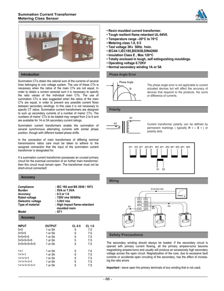
Summation Current Transformer Metering Class Sensor • Resin moulded current transformer. • Tough resilient flame retardant UL-94V0. • Temperature range –20°C to 70°C • Metering class 1.0, 0.5 • Test voltage 3Kv 50Hz. 1min. • IEC44-1,IEC185,BS3938,DIN42600 • Insulation Class E , Max 120°C • Totally enclosed in tough, self extinguishing mouldings. • Operating voltage 0.72KV • Normal secondary winding 1A or 5A Introduction Phase Angle Error Summation CTs obtain the cetorial sum of the currents of several lines belonging to one voltage system. The use of these CTs is necessary when the ratios of the main CTs are not equal, In order to obtain a correct vectorial sum it is necessary to specify the ratio values of the individual main CTs. The use of summation CTs is also suggested when the ratios of the main CTs are equal, in order to prevent any possible current flows between secondary windings. In this case it is not necessary to specify CT ratios. Summation current transformers are designed to sum up secondary currents of a number of mains’ CTs. The numbers of mains’ CTs to be totaled may ranged from 2 to 6 and are available for 1A or 5A secondary current ratings. Phase Angle Ip Is Polarity X1 H1 Summation current transformers enable the summation of several synchronous alternating currents with similar phase position, though with different loaded phase shifts. In the connection of main transformers of differing nominal transmissions ratios care must be taken to adhere to the assigned connection that the input of the summation current transformer is designated for. Current transformer polarity can be defined by permanent markings ( typically H 1 – X 1 ) or polarity dots. 1P1 1P2 2P1 2P2 3P1 3P2 4P1 4P2 5P1 5P2 6P1 6P2 If a summation current transformer possesses an unused primary circuit for the eventual connection of an further main transformer, then this circuit must remain open. The transformer must not be short-circuit connected! Accuracy The phase angle error is not applicable to current actuated devices but will affect the accuracy of devices that respond to the products, the sums or difference of currents. S1 S2 Wiring Compliance Burden Accuracy Rated voltage Dielectric voltage Type of material : IEC 185 and BS 3938 / 1973 : 5VA or 7.5VA : 0.5 or 1.0 : 720V rms 50/60Hz : 3.0kV rms : High impact flame-retardant moulded resin : ST1 Model Accuracy INPUT 5+5 5+5+5 5+5+5+5 5+5+5+5+5 5+5+5+5+5+5 OUTPUT 1 or 5A 1 or 5A 1 or 5A 1 or 5A 1 or 5A 1+1 1+1+1 1+1+1+1 1+1+1+1+1 1+1+1+1+1+1 1 or 5A 1 or 5A 1 or 5A 1 or 5A 1 or 5A CL 0.5 5 5 5 5 5 5 5 5 5 5 CL 1.0 7.5 7.5 7.5 7.5 7.5 7.5 7.5 7.5 7.5 7.5 Safety Precautions The secondary winding should always be loaded. If the secondary circuit is opened with primary current flowing, all the primary ampere-turns become magnetizing ampere-turns and usually will produce an excessively high secondary voltage across the open circuit. Magnetization of the core, due to excessive fault currents or accidental open circuiting of the secondary, has the effect of increasing the ratio errors Important : leave open the primary terminals of any winding that is not used. - 66 -


