How to Set Up Your SRX1500 Services Gateway
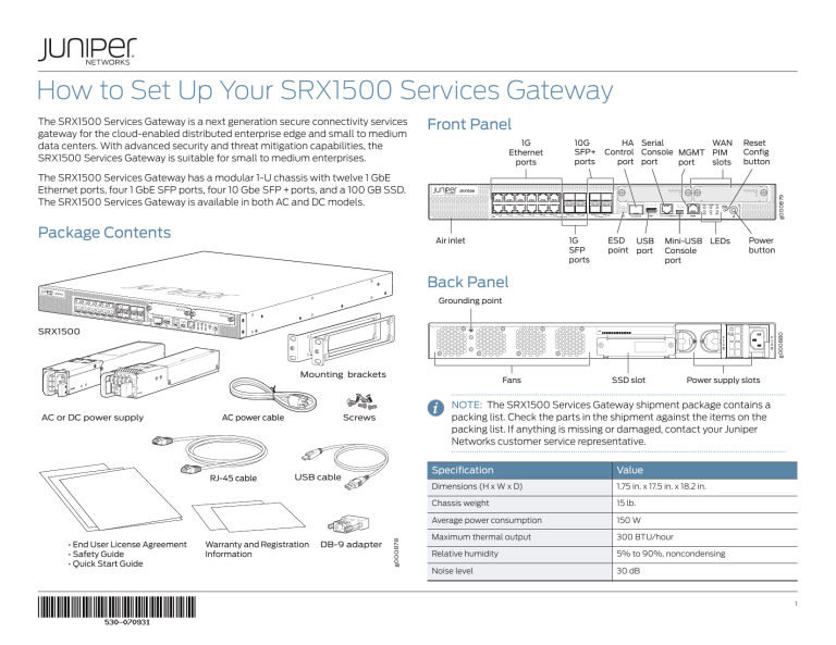
The SRX1500 Services Gateway is a next generation secure connectivity services
gateway for the cloud-enabled distributed enterprise edge and small to medium
data centers. With advanced security and threat mitigation capabilities, the
SRX1500 Services Gateway is suitable for small to medium enterprises.
Front Panel
1G
Ethernet
ports
10G
SFP+
ports
HA Serial
WAN
Control Console MGMT PIM
port port
port
slots
Reset
Config
button
Package Contents
g000879
The SRX1500 Services Gateway has a modular 1-U chassis with twelve 1 GbE
Ethernet ports, four 1 GbE SFP ports, four 10 Gbe SFP + ports, and a 100 GB SSD.
The SRX1500 Services Gateway is available in both AC and DC models.
Air inlet
1G
SFP
ports
ESD
point
USB
port
Mini-USB LEDs
Console
port
Power
button
Back Panel
Grounding point
g000880
SRX1500
Mounting brackets
RJ-45 cable
• End User License Agreement
• Safety Guide
• Quick Start Guide
USB cable
Warranty and Registration
Information
DB-9 adapter
SSD slot
Power supply slots
NOTE: The SRX1500 Services Gateway shipment package contains a
packing list. Check the parts in the shipment against the items on the
packing list. If anything is missing or damaged, contact your Juniper
Networks customer service representative.
Screws
AC power cable
g000878
AC or DC power supply
Fans
Specification
Value
Dimensions (H x W x D)
1.75 in. x 17.5 in. x 18.2 in.
Chassis weight
15 lb.
Average power consumption
150 W
Maximum thermal output
300 BTU/hour
Relative humidity
5% to 90%, noncondensing
Noise level
30 dB
1
Initial Configuration Process
Gather information about your network and the configuration settings that you
will use to configure the device.
Install Device
in a Rack
Connect
the Grounding
Cable
Power On
the Device
Connect
to the
Console Port
Configure
Root Authentication
and Management
Interface
Log in
to the CLI
Required
Root authentication
IP address of management interface
Default route
Optional
g043458
Gather Configuration Information
Install the Device in a Rack
Hostname
NOTE: Installing the device in a rack requires two people: one person
lifts the device while the other secures it to the rack.
IPv4 address of physical interfaces
Trust zone interface
1. Position a mounting bracket on each side of the chassis. Use a number-2
Phillips screwdriver to install the screws that secure the mounting brackets to
the chassis.
Untrust zone interface
Security policies
Factory-Default Settings
Interface
Security Zone
DHCP State
IP Address
ge-0/0/0
untrust
Client
Dynamically assigned
ge-0/0/1
trust
Server
192.168.2.1/24
ge-0/0/2
trust
Server
192.168.3.1/24
ge-0/0/3
trust
Server
192.168.4.1/24
xe-0/0/16
trust
Server
192.168.4.1/24
xe-0/0/17
trust
Server
192.168.5.1/24
Security Policies
Source Zone
Destination Zone
Policy Action
trust
trust
permit
trust
untrust
permit
g000871
Interfaces
2. Have one person grasp the sides of the device, lift it, and position it in the rack.
Align the bottom hole in each mounting bracket with a hole in each rack rail,
making sure that the chassis is level.
3. Have a second person install a mounting screw into each of the two aligned
holes. Use a number-2 Phillips screwdriver to tighten the mounting screws.
NAT Rules
Source Zone
Destination Zone
Policy Action
trust
untrust
Source NAT to untrust zone
interface
How to Set Up Your SRX1500 Services Gateway
2
2. Place the grounding cable lug over the grounding point on the upper rear of
the chassis.
4. Install the second screw in each mounting bracket.
CAUTION: A licensed electrician must attach a cable lug to the
grounding cable. A cable with an incorrectly attached lug can damage
the device.
4. Secure the grounding cable lug to the grounding point with the screw. Apply
between 6 lb-in. (0.67 N-m) and 8 lb-in. (0.9 N-m) of torque to tighten the
screws.
NOTE: The device must be permanently connected to ground during
normal operation.
Power On the Device
g000872
NOTE: Before connecting the device to the power supply, attach an
electrostatic discharge (ESD) grounding strap to your bare wrist, and
connect the strap to the ESD point on the chassis.
5. Verify that the mounting screws on one side of the rack are aligned with the
mounting screws on the opposite side and that the device is level.
1. If you are using the AC model, perform the following steps:
a. Insert the appliance coupler end of the power cord into the appliance inlet
on the power supply and the power cord plug into an external AC power
source receptacle. Use a power cord retainer to hold the power cord in
place.
Connect the Grounding Cable
Grounding point
on the chassis
Grounding
screw
Grounding
lug
Power cord
Power cord
retainer
g000883
Locking
washer
b. Turn on the power to the AC power receptacle
g000882
2. If you are using the DC model, perform the following steps:
1. Connect the grounding cable to a proper earth ground.
WARNING: Before performing the following procedure, ensure that
there is no power in the DC circuit. To ensure that all power is cut off,
locate the circuit breaker on the panel board that services the DC circuit,
switch the circuit breaker to the OFF (0) position, and tape the switch
handle of the circuit breaker in the OFF position.
How to Set Up Your SRX1500 Services Gateway
3
a. Ensure that the voltage across the DC power source cable leads is 0 V
and that the cable leads do not become active while you are connecting
DC power.
3. Note the following LED indications. Wait until the status LED (STAT) is solid
green before proceeding to the next step.
•• The cable with very high resistance (indicating an open circuit) to chassis
ground will be connected to the V- (input) DC power input terminal.
•• The cable with very low resistance (indicating a closed circuit) to chassis
ground will be connected to the V+ (return) DC power input terminal.
g000881
b. Verify that the DC power cables are correctly labeled before making
connections to the power supply. In a typical power distribution scheme
where the return is connected to chassis ground at the battery plant, you
can use a multimeter to verify the resistance of the -48V and RTN DC
cables to chassis ground:
LED
State
STAT
•• Solid green (operating normally)
ALARM
•• Solid amber (noncritical alarm)
c. Remove the clear plastic cover from the terminal studs on the faceplate.
•• Solid red (critical alarm)
d. Remove the screws on the terminals by using a Phillips (+) screwdriver,
number 2.
SSD
e. Secure the power source cables to the power supplies by screwing the ring
lugs attached to the cables to the appropriate terminals by using the screw
from the terminals.
•• Blinking green (the services gateway is transferring data to
or from the SSD storage device)
PWR
•• Solid green (receiving power)
•• Off (no alarms)
•• Off (SSD storage device not present)
•• Secure each positive (+) DC source power cable lug to a RTN (return)
terminal.
•• Secure each negative (–) DC source power cable lug to a -48V (input)
terminal.
•• Blinking green (receiving power—the services gateway is in
the bootup phase before OS initialization)
•• Solid red (power supply unit failure)
HA
•• Solid green (all HA links are available)
•• Solid amber (some HA links are unavailable)
•• Solid red (device is inoperable because of a monitor failure)
RPS
•• Solid green (redundant power supply is operating normally)
g000876
•• Off (no redundant power supply)
f. Replace the clear plastic cover over the terminal studs on the faceplate.
g. Remove the tape from the switch handle of the circuit breaker on the panel
board that services the DC circuit and switch the circuit breaker to the ON
(|) position.
How to Set Up Your SRX1500 Services Gateway
4
Connect to the Console Port
1. Attach an ESD grounding strap to your bare wrist, and connect the strap to
the ESD point on the chassis.
2. Plug one end of the Ethernet cable into the Console port on your services
gateway.
2. At the (%) prompt, type cli to start the CLI and press Enter. The prompt
changes to an angle bracket (>) when you enter the CLI operational mode.
root%cli
root>
3. At the (>) prompt, type configure and press Enter. The prompt changes from
> to # when you enter the configuration mode.
root> configure
Entering configuration mode
[edit]
root#
Console port
4. Set the root authentication password by entering a cleartext password, an
encrypted password, or an SSH public key string (DSA or RSA).
g000889
root# set system root-authentication plain-text-password
New password: password
Retype new password: password
Ethernet port
3. Connect the other end of the Ethernet cable to the Ethernet port on the
management device.
If the management device has a serial port, then use the RJ-45 to DB-9 serial
port adapter supplied with your services gateway. Use the following values to
configure the serial port:
Baud rate—9600; Parity—N; Data bits—8; Stop bits—1; Flow control—None
NOTE: Alternately, you can use the USB cable to connect to the miniUSB console port on the services gateway. To use the USB console port,
you must download a USB driver to the management device from
http://www.juniper.net/support/downloads/group/?f=junos.
5. Commit the configuration to activate it on the device.
root# commit
6. Configure the IP address and prefix length for the Ethernet management
interface on the device.
root# set interfaces fxp0 unit 0 family inet address
address/prefix-length
7. Configure the default route.
root# set routing-options static route 0.0.0.0/0 nexthop <gateway>
8. Enable Web access to launch J-Web.
root# set system services web-management http
9. Commit the configuration changes.
Configure Root Authentication
and the Management Interface
root# commit
Before you can use J-Web to configure your device, you must access the CLI to
configure the root authentication and the management interface.
1. Log in to the device as root. When the device is powered on with the factorydefault configuration, you do not need to enter a password.
Launch a Web browser from the management device and access the services
gateway using the URL http://<device management IP address>. The J-Web
login page is displayed. This indicates that you have successfully completed the
initial configuration and that your SRX1500 Services Gateway is ready for use.
How to Set Up Your SRX1500 Services Gateway
5
Configure Interfaces, Zones, and Policies Using
J-Web (Option 1)
1. Log in as the root user.
2. Configure the hostname:
a. Select Configure>System Properties>System Identity, and then select
Edit.
b. Enter the hostname and click OK.
d. In the Host Inbound Traffic Zone tab, select protocols all and services all
for the trust zone.
e. Repeat Step a through Step c and assign another interface to an untrust
zone.
f. In the Host Inbound Traffic Zone tab, select services dhcp and tftp for the
untrust zone.
g. Select Commit>Commit to apply the configuration changes.
5. Configure security policies:
c. Select Commit>Commit to apply the configuration changes.
3. Configure any two physical interfaces:
a. Select Configure>Interfaces>Ports and select a physical interface you
want to configure.
a. Select Configure>Security>Security Policy and click Add.
b. Select Add>Logical Interface.
b. Enter the policy name and set the policy action to permit.
c. Set Unit = 0 and select the check box for IPv4 Address.
c. Select Zone and set the From Zone to trust and the To Zone to untrust.
d. Click Add to enter the IPv4 address and click OK.
d. Select the source IP address, destination IP address, and application from
the available list and click OK.
e. Select Commit>Commit to apply the configuration changes
e. Repeat Step a through Step d to configure a policy from a trust zone to a
trust zone.
4. Configure zones and assign interfaces:
a. Select Configure>Security>Zones/Screens and click Add.
f. Select Commit>Commit to apply the configuration changes.
b. Enter the zone name as trust and set zone type to Security.
c. Select the interfaces to assign to the zone and click OK.
How to Set Up Your SRX1500 Services Gateway
6
Configure Interfaces, Zones, and Policies
Using CLI (Option 2)
1. Log in as the root user.
2. Configure the name of the services gateway:
6. Configure basic security policies:
root# set security policies from-zone trust to-zone
untrust policy policy-name match source-address any
destination-address any application any
root# set security policies from-zone trust to-zone
untrust policy policy-name then permit
root@# set system host-name <host-name>
3. Configure the IP address and prefix length for the services gateway Ethernet
interface:
root# set interfaces fxp0 unit 0 family inet address
<address/prefix-length>
4. Configure the traffic interface:
root# set interfaces ge-0/0/0 unit 0 family inet address
<address/prefix-length>
root# set interfaces ge-0/0/1 unit 0 family inet address
<address/prefix-length>
5. Configure basic security zones and bind them to traffic interfaces:
root# set security zones security-zone trust hostinbound-traffic system-services all
root# set security zones security-zone trust hostinbound-traffic protocols all
root# set security zones security-zone untrust
interfaces ge-0/0/0
root# set security policies from-zone trust to-zone
trust policy policy-name match source-address any
destination-address any application any
root# set security policies from-zone trust to-zone
trust policy policy-name then permit
NOTE: The actual configuration of the policies depends on your
requirements.
7. Check the configuration for validity and then commit the configuration:
root# commit check
configuration check succeeds
root# commit
8. Display the configuration to verify that it is correct:
root# show
root# set security zones security-zone trust interfaces
ge-0/0/1
root# set security zones security-zone untrust
interfaces ge-0/0/0.0 host-inbound-traffic systemservices dhcp
root# set security zones security-zone untrust
interfaces ge-0/0/0.0 host-inbound-traffic systemservices tftp
How to Set Up Your SRX1500 Services Gateway
7
Verify the Settings
Reset the Configuration
1. Connect port 0/0 to the ISP device to obtain a dynamic IP address.
Pressing and holding the RESET CONFIG button for 5 seconds or more deletes
all configurations (backup configurations and rescue configuration) on the
device, and loads and commits the factory configuration.
2. Access http://www.juniper.net to ensure that you are connected to the
Internet. This connectivity ensures that you can pass traffic through the
services gateway.
Next Steps
•• Configure AppSecure Services:
•• Configure Application Tracking. See Example: Configuring AppTrack.
•• Configure Application Firewall. See Example: Configuring Application Firewall Rule Sets Within a Security Policy.
•• Configure Application QoS. See Example: Configuring AppQoS.
If the page does not load, perform the following checks to see if you can identify
the problem:
•• Verify your configuration settings, and ensure that you have applied the
configuration.
•• Configure Unified Threat Management (UTM):
•• Configure Sophos antivirus protection. See Sophos Antivirus Configuration
Overview.
•• Configure content filtering. See Content Filtering Configuration Overview.
•• Check if the ISP-supplied device connecting your SRX Series device to the
Internet is turned on and working properly. Try turning it off and on again.
•• Enable IDP services. See Enabling IDP in a Security Policy.
After you complete these steps, the SRX Series device can pass traffic from any
trust port to the untrust port.
Reference
Supported Transceivers
Junos OS Documentation
http://www.juniper.net/techpubs/en_US/release-independent/junos/
information-products/pathway-pages/srx-series/product/index.html
For information on transceivers supported on the SRX1500 Services Gateway,
see SRX Series Services Gateway Transceiver Guide.
Technical Support
http://www.juniper.net/support/requesting-support.html
Power Off the Device
SRX1500 Services Gateway Hardware Guide
http://www.juniper.net/techpubs/en_US/release-independent/junos/
information-products/pathway-pages/srx-series/product/index.html
To power off the device, press the Power button on the front of the device and
hold it for 10 seconds.
After powering off a power supply, wait for at least 60 seconds before turning it
back on.
NOTE: Graceful shutdown is not supported on the SRX1500 Services
Gateway.
Copyright © 2016, Juniper Networks, Inc. All rights reserved.
Juniper Networks, Junos, Steel-Belted Radius, NetScreen, and ScreenOS are registered trademarks of Juniper Networks, Inc. in the United States and other countries. The Juniper Networks Logo, the Junos logo, and JunosE are trademarks of Juniper
Networks, Inc. All other trademarks, service marks, registered trademarks, or registered service marks are the property of their respective owners. Juniper Networks assumes no responsibility for any inaccuracies in this document. Juniper Networks
reserves the right to change, modify, transfer, or otherwise revise this publication without notice. Part Number: 530-070931 Revision 01, June 2016.


