XCL Series Switchbox
advertisement
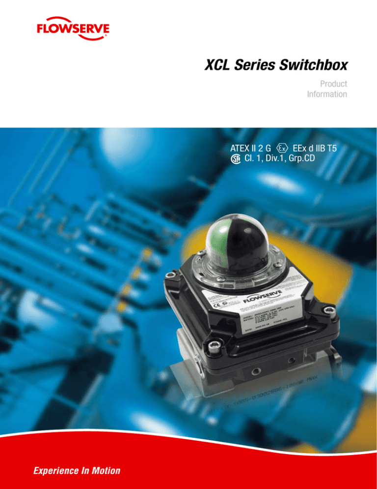
XCL Series Switchbox Product Information ATEX II 2 G EEx d IIB T5 Cl. 1, Div.1, Grp.CD C. B. A. A. Tool-free adjustment B. Pre-wired terminal strip C. Dual 3/4 NPT or M25x1,5 conduit entries Features Quick-set cams Captive Cover Screws Tool free adjustment of switch trip is accomplished simply by pushing or pulling the cam and rotating it to the new position. Cams are spring-loaded and splined to maintain switch setting in any installed position. Limit switches Multiple options available: Electromechanical, Amplified proximity, Namur proximity, SPDT, DPDT. Up to 4 pcs possible. Permit calibration without potential for losing screws. Watertight protection IEC 529 IP67 / NEMA 4X ATEX approved Explosion proof ATEX II 2 G EEx d IIB T5 CSA approved Div.1, Cl.1, Group C-D, Div.1, Cl.2, Group E-G Cable entries Dual 3/4 NPT (XCL) or M25x1,5 (XML) conduit entries as standard. Terminal strip Pre-wired, multi-point terminal strip with extra strip as standard for optional solenoid valve. Position indicator Bolt-on Dome indicator for high contrast wide angle viewing. A flat lid without indicator is also available. XCL series switchbox is designed to be directly and easily mounted onto actuators having connections according to Namur VDI/VDE 3845, in order to reduce switchbox/actuator mounting time. 4–20 mA Transmitter 2 x SPDT switches Type M1 2 x SPDT Sabre Switch Switch Options Switch Option Manufacturer Part Number Load Capacity M1 - SPDT Mechanical Honeywell MicroSwitch V7-1C13D8-201 15 A (1/2 HP) at 125 V AC/ 0,5 A at 125 V DC MG - SPDT Gold Mechanical Honeywell MicroSwitch V7-1D11D8-201 1 A at 125 V AC/ 50 mA at 24 V DC M3 - DPDT Mechanical Cherry E19-00A 15 A (3/4 HP) at 125 V AC MB - DPDT Mechanical Licon 22-104 10 A (1/2 HP) at 125 V AC P4 - SPST Proximity Aleph PS-6132 0.35 A at 140 V AC / 1 A at 50 V DC (50 W Max.) P5 - SPDT Proximity Hamlin 59135-030 0.25 A at 120 V AC / 0.25 A at 28 V DC (3 W Max.) PE - SPDT Sabre Proximity Flowserve XA0199 1 A at 120 V AC / 1 A at 24 V DC (25 W Max.) PP - SPDT Phazer Proximity Flowserve XA0155 3 A at 120 V AC / 2 A at 24 V DC (100 W Max.) PT - SPST BRS Proximity Flowserve XA0157 3 A at 120 V AC / 0.5 A at 24 V DC N8 - Solid State Proximity Pepperl + Fuchs NJ2-V3-N NP- Solid State Proximity Pepperl + Fuchs SJ3.5-N NQ - Solid State Proximity Pepperl + Fuchs NJ4-12GK-N NR - Solid State Proximity Pepperl + Fuchs NJ4-12GM40-E1 PNP Sinking / 200 mA max. Current / 10–60 V DC NS - Solid State Proximity Pepperl + Fuchs NJ4-12GM40-E2 NPN Sourcing / 200 mA max. Current / 10–60 V DC NJ - Solid State Proximity1 IFM Efector IN-2002-ABOA 0.35 A at 250 V AC / 0.1 A at 250 V DC NU - SPDT GO Proximity GO 35-13319-A1A 4 A at 120 V AC / 3 A at 24 V DC NAMUR Sensor Output / 5–25 V DC Supply Load Current <1 mA (w/Target) / > 3 mA w/out Target ATEX XCL series switchbox is ATEX approved. Explosion proof ATEX II 2 G EExd IIB T5 and can be installed in hazardous areas. CSA Div.1, Cl.1, Group C–D, Div.1, Cl.2, Group E–G. Materials Cam shaft: AISI 304 Housing: Aluminium, powder coated Screws, washers, springs, rings: AISI 303 Dome Indicator: Polycarbonate Label: Polyester AS-Interface (AS-i) XCL series can be equiped with optional AS-i communication capabilities. This technology offers a very simple, flexible and cost effective network system. XCL Series Coding Brand sticker P Shaft N Connections (cable entry) XCL XML Indicator option 1 U Qty of switches 0 1 2 4 Switch options M1 MG M3 MB P4 P5 PE PP PT N8 NQ NR NS NP NJ NU FZ Certificate 14 18 Analog Output 0 T D A B C Wiring options 0 Minimun extra terminals 2 4 6 Acessories 0 L P V Housing/Surface treatment 0 Example PNXCLU2M1-1800-200 PMV Namur VDI/VDE 3845 2 x 3/4 NPT 2 x M25 x 1,5 Flat cover without indicator Dome, Red/Green 0 switches 1 switch 2 switches 4 switches SPDT Mechanical switches 250VAC 10A SPDT Mechanical switches gold plated DPDT Mechanical Cherry DPDT Mechanical Licon SPST proximity SPDT proximity Sabre SPDT proximity Phazer II SPDT proximity BRS SPST Phazer II proximity P+F NJ2 V3 N (Namur) P+F NJ4-12GK-N (Namur) P+F 12GM40-E1 (3 wire NPN NO) P+F 12GM40-E2 (3 wire PNP NO) P+F SJ 3,5-N (Namur) IFM IN -2002-ABOA GO proximity 35-13319-A1A AS-i controller card 2,0 incl. 2 proximity switches General Purpose ATEX II 2 G EEx d IIB T5 / CSA Div.1, Cl.1, GRP CD None 4-20 mA transmitter 180 deg 4-20 mA transmitter 0-1k Ohm Pot 0-5k Ohm Pot 0-10k Ohm Pot None 2 (standard) 4 (Optional) 6 (Optional, not possible for all switch options) None Cover bolts lubricated with grease 180’ Pot ( for analog options: A, B, C) Viton O-rings Black polyester powder coat Dimensions (mm) 19 19 19 19 3/4" NPT OR M25-1.5 CONDUIT ENTRY 3/4" NPT OR M25-1.5 (BOTH SIDES) CONDUIT ENTRY (BOTH SIDES) 5/16-18 UNC X 9 DEEP (2) PLACES 5/16-18 UNC X 9 DEEP (2) PLACES M6-1 X 9 DEEP (4) PLACES M6-1 X 9 DEEP (4) PLACES SIDE MOUNTING SURFACE SIDE MOUNTING SURFACE 18 18 29 29 76 76 157 157 Ø92 Ø92 18 68 68 29 1829 68 231 MINIMUM CLEARANCE FOR ADJUSTMENTS 231 MINIMUM CLEARANCE AND INSPECTION FOR ADJUSTMENTS AND INSPECTION 135 68 135 148 148 54 54 5/16-18 UNC X 9 DEEP (4) PLACES 5/16-18 UNC X 9 DEEP (4) PLACES 28.6 17.7 17.7 17.7 28.6 28.6 17.7 28.6 3 3 17 17 10 10 29 29 42 42 5/16-18 UNC X 9 DEEP EXTERNAL GROUND SCREW LOCATION 5/16-18 UNC X 9SIDES) DEEP (BOTH EXTERNAL GROUND SCREW LOCATION (BOTH SIDES) 87 87 23 Ø10 23 25 25 Ø10 4 FLATS (NAMUR SHAFT) 4 FLATS (NAMUR SHAFT) 127 MINIMUM CLEARANCE FOR 127 MINIMUM ADJUSTMENTS CLEARANCE FOR AND INSPECTION ADJUSTMENTS AND INSPECTION Palmstierna International AB Korta Gatan 9 SE-171 54 Solna SWEDEN Tel: +46 (0) 8 555 106 00 Fax: +46 (0) 8 555 106 01 E-mail: infopmv@flowserve.com UK Flowserve Abex Road Newbury, Berkshire, RG14 5EY UK Tel: +44 (0) 1635 46 999 Fax: +44 (0) 1635 36 034 E-mail: pmvukinfo@flowserve.com Italy Flowserve Spa Via Prealpi, 30 20032 Cormano (Milano) ITALY Tel: +39 (0) 2 663 251 Fax: +39 (0) 2 615 18 63 E-mail: infoitaly@flowserve.com p/n: FCD PMENBR0010-02 Hazardous Locations Rätt Grafiska AB Ordernr: 23282 ATEX II 2 G EEx d IIB T5 ATEX Demko 04 Atex 0416173 Div.1, Class 1, Group C,D Flowserve Corporation has established industry leadership in the design and manufacture of its products. When properly selected, this Flowserve product is designed to perform its intended function safely during its useful life. However, the purchaser or user of Flowserve products should be aware that Flowserve products might be used in numerous applications under a wide variety of industrial service conditions. Although Flowserve can (and often does) provide general guidelines, it cannot provide specific data and warnings for all possible applications. The purchaser/user must therefore assume the ultimate responsibility for the proper sizing and selection, installation, operation, and maintenance of Flowserve products. The purchaser/user should read and understand the Installation and Maintenance (I & M) instructions included with the product, and train its employees and contractors in the safe use of Flowserve products in connection with the specific application. While the information and specifications contained in this literature are believed to be accurate, they are supplied for informative purposes onlyand should not be considered certified or as a guarantee of satisfactory results by reliance thereon. Nothing contained herein is to be construedas a warranty or guarantee, express or implied, regarding any matter with respect to this product. Because Flowserve is continually improving andupgrading its product design, the specifications, dimensions and information contained herein are subject to change without notice. Should any question arise concerning these provisions, the purchaser/user should contact Flowserve Corporation at any one of its worldwide operations or offices. ©2007 Flowserve Corporation, Irving, Texas, USA. Flowserve and PMV are registered trademarks of Flowserve Corporation. Asia Pacific Headquarters Flowserve Pte Ltd. No. 12 Tuas Avenue 20 REPUBLIC OF SINGAPORE 638824 Tel: +65 (0) 687 98900 Fax: +65 (0) 686 24940 Germany Flowserve Im grossen Rohr 2 65549 Limburg/Lahn GERMANY Tel: +49 (0) 6431 9661 0 Fax: +49 (0) 6431 9661 30 E-mail: pmvgermany@flowserve.com South Africa Flowserve Unit 1, 12 Director Road Spartan Ext. 2 1613 Kempton Park, Gauteng SOUTH AFRICA Tel: +27 (0) 11 397 3150 Fax: +27 (0) 11 397 5300 The Netherlands Flowserve Flow Control Benelux Rechtzaad 17 4703 RC Roosendaal THE NETHERLANDS Tel: +31 (0) 30 6771946 Fax: +27 (0) 30 6772471 E-mail: fcbinfo@flowserve.com Flowserve Hanwei Building No. 7 Guanghua Road ChaoYang District 100004 Beijing CHINA Tel: +86-10-592 106 00 Fax: +86-10-656 127 02 www.pmv.nu


