Waste Heat Recovery through Air Conditioning System
advertisement

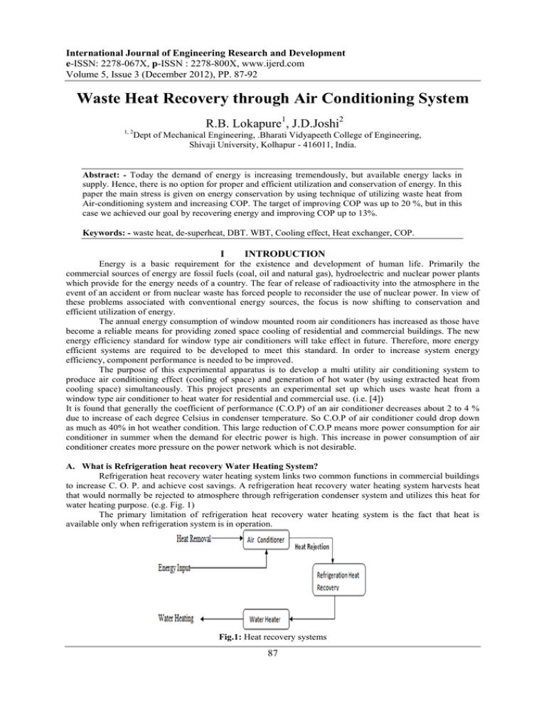
International Journal of Engineering Research and Development e-ISSN: 2278-067X, p-ISSN : 2278-800X, www.ijerd.com Volume 5, Issue 3 (December 2012), PP. 87-92 Waste Heat Recovery through Air Conditioning System R.B. Lokapure1, J.D.Joshi2 1, 2 Dept of Mechanical Engineering, .Bharati Vidyapeeth College of Engineering, Shivaji University, Kolhapur - 416011, India. Abstract: - Today the demand of energy is increasing tremendously, but available energy lacks in supply. Hence, there is no option for proper and efficient utilization and conservation of energy. In this paper the main stress is given on energy conservation by using technique of utilizing waste heat from Air-conditioning system and increasing COP. The target of improving COP was up to 20 %, but in this case we achieved our goal by recovering energy and improving COP up to 13%. Keywords: - waste heat, de-superheat, DBT. WBT, Cooling effect, Heat exchanger, COP. I INTRODUCTION Energy is a basic requirement for the existence and development of human life. Primarily the commercial sources of energy are fossil fuels (coal, oil and natural gas), hydroelectric and nuclear power plants which provide for the energy needs of a country. The fear of release of radioactivity into the atmosphere in the event of an accident or from nuclear waste has forced people to reconsider the use of nuclear power. In view of these problems associated with conventional energy sources, the focus is now shifting to conservation and efficient utilization of energy. The annual energy consumption of window mounted room air conditioners has increased as those have become a reliable means for providing zoned space cooling of residential and commercial buildings. The new energy efficiency standard for window type air conditioners will take effect in future. Therefore, more energy efficient systems are required to be developed to meet this standard. In order to increase system energy efficiency, component performance is needed to be improved. The purpose of this experimental apparatus is to develop a multi utility air conditioning system to produce air conditioning effect (cooling of space) and generation of hot water (by using extracted heat from cooling space) simultaneously. This project presents an experimental set up which uses waste heat from a window type air conditioner to heat water for residential and commercial use. (i.e. [4]) It is found that generally the coefficient of performance (C.O.P) of an air conditioner decreases about 2 to 4 % due to increase of each degree Celsius in condenser temperature. So C.O.P of air conditioner could drop down as much as 40% in hot weather condition. This large reduction of C.O.P means more power consumption for air conditioner in summer when the demand for electric power is high. This increase in power consumption of air conditioner creates more pressure on the power network which is not desirable. A. What is Refrigeration heat recovery Water Heating System? Refrigeration heat recovery water heating system links two common functions in commercial buildings to increase C. O. P. and achieve cost savings. A refrigeration heat recovery water heating system harvests heat that would normally be rejected to atmosphere through refrigeration condenser system and utilizes this heat for water heating purpose. (e.g. Fig. 1) The primary limitation of refrigeration heat recovery water heating system is the fact that heat is available only when refrigeration system is in operation. Fig.1: Heat recovery systems 87 Waste Heat Recovery Through Air Conditioning System. B. Principle of Refrigeration Heat Recovery System Desuperheater is a particular type refrigeration heat recovery system that recovers only the more readily available superheat energy from the host system. They can be either direct or indirect type. In present refrigeration heat recovery system indirect type of system is used. C. Typical Refrigeration Heat Recovery System implemented A refrigeration heat recovery device is indirect type of system in which a refrigerant to water heat exchanger is installed between the host refrigeration system compressor and condenser. Water is circulated through one side of heat exchanger and hot refrigerant gas from the compressor is routed through the other side. Heat is transferred from the hot refrigerant gas to the water. Most refrigerant heat recovery devices are desuperheaters. Superheat refers to heat stored in the refrigerant vapor when it is heated above the temperature at which it evaporates for a given pressure . Acting as a desuperheater, a heat recovery device cools the refrigerant only to the saturation point. No condensing takes place in the desuperheater .Under typical conditions a desuperheater can remove about 10- 30 % of the total heat that would have been rejected by the condenser. A heat recovery device may also be designed to do condensing rather than just desuperheating and more heat can be extracted but at a lower temperature. With excessive sub cooling (reduction of liquid refrigerant temperature below the saturation point) in the condenser at low outdoor temperature, problem can occur with low compressor head pressure, improper expansion device operation from inadequate pressure drop, and liquid slugging in the compressor. II. DESIGN OF HEAT RECOVERY SYSTEM The heat recovery system is designed for the available desuperheating heat in the window air conditioner. The available heat is calculated by using the rated conditions of the window air conditioner and after that the heat exchanger design is done for that heat recovery. A. The Design Process The design process will be done based on following guidelines. 1. The heat recovery system will serve as a retrofit for an existing air conditioning unit. 2. It must include provisions for bypassing the heat recovery system. These bypasses must allow normal operations of the air conditioner without heat recovery. 3. The heat recovery system must not require pumps rather it should utilize thermo-siphon effects or tap water. 4. All components of the system should be instrumented with thermometer and manometer. 5. The material must endure flow and temperature variations and be resistant to corrosion. 6. The heat recovery system components, such as tubes and fittings, must be standardized to lower the cost. B. Technical Specification of the Set Up AIR CONDITIONER: BLUE STAR MODEL NO. : WAM241R SERIAL NO. : WAM241R050474 EQUIPMENT RATING: SINGLE PHASE, 230 V, 50 HZ, 13 A. POWER RATING: 2.5 kW REFRIGERANT: R-22 ( CHCLF2) NORMAL CAPACITY: 1.5 TR AT COMPRESSOR: HERMITICALLY SEALED ROTARY CONDENSER: FORCED CONVECTION AIR COOLED EVAPORATOR: FORCED CONVECTION AIR COOLED THERMOSTAT: ON PANEL ENERGY METER: FOR COMPRESSOR PROVIDED PRESSURE GAUGE: 1 NO. FOR SUCTION PRESSURE AND 1 NO. FOR DISCHARGE PRESSURE TEMPERATURE INDICATOR: DIGITAL THERMOMETER INDICATOR AIR FLOW MEASUREMENT: BY INCLINED TUBE MANOMETER C. Methodology 1. Calculation of energy supplied for refrigeration effect 2. Measurement of heat extracted from cooling space. 3. Design of heat exchanger unit 88 Waste Heat Recovery Through Air Conditioning System. 4. Measurement of heat collected in heat exchanger unit. 5. Calculation of COP for normal air conditioning system 6. Calculation of COP for air conditioning system with exhaust heat collection using heat exchanger. 7. Comparison of COP in both above cases. 8. Conclusion III. DESIGN PROCESS 1. Calculation of energy supplied for refrigeration effect Input power to Air conditioner unit = 2.5 kW = 2500 W = 2500 J / sec 2. Measurement of heat extracted from cooling space. Following observations were taken at evaporator. Table 1: Temperature of Air Temp. of DBT 0 C WBT 0 C air Inlet 33 25 Outlet 23 19 Enthalpy kJ / Kg 77 ( H1 ) 54 ( H2 ) Heat extracted from cooling space = H1 – H2 = 77-54 (i.e. Table1) = 23 kJ/Kg of air flow Air flow rate = 0.2215 Kg/sec Hence, heat extracted in evaporator by refrigerant /sec = 23 * 0.2215 = 5.0945 kJ / sec = 5094.5 J/sec = 5094.5 W = Refrigeration Effect 3. Design of Heat Exchanger Unit To find the heat removed from refrigerant during desuperheated conditions: Compressor inlet = 4.83 bar Compressor Outlet = 18.27 bar Evaporator Temperature = -1OC Condenser Temperature = 47OC Cooling Capacity = 1.5 TR =1.5*3.5= 5.3505kW Fig.2: Pressure –enthalpy Fig.3:Temp.-entropy 89 Waste Heat Recovery Through Air Conditioning System. To find temp. T2 We have, S2= S2‟ + 2.3 Cp log (T2/T2‟) (i.e. Fig.3) 1.7521=1.6893 + 2.3*1.0256 log (T2/320) 1.7521= 2.3588 log (T2/320) = 1.7521 – 1.6893 T2= 68.29OC Refrigerating effect = h1-hf3 = 404.68 – 259.1 = 145.58 kJ/kg (i.e. Fig.2) Mass flow rate (mR) = 5.3505/145.58 = 0.03675 kg/sec Heat available for desuperheating (Q) = mR (h2- h2’) = 0.03675(437.92 – 417.18) = 0.7651 kW Q= 765.13 W (i.e. [3]) HEAT EXCHANGER UNIT. GIVEN DATA:Inner diameter of tube (Di) = 8.4 mm Outer diameter of tube (DO) = 10 mm Thickness of tube (t) = 0.8 mm Material selected = Copper. Thermal conductivity (k) = 380 W/m k. Fouling factor for Refrigerant =0.00017. Fouling factor for water =0.00017. 1) Heat transfer coefficient for refrigerant side hi = 898 W/m2k. 2) Heat transfer coefficient for water side ho = 151.58 W/m2k. 3) Overall heat transfer coefficient. 1/U =1/hi +1/ho + dx/k + Fr + Fw. =1/898+1/151.48+ 0.8*10-3/380+0.00017+0.00017 =1/0.00804 U= 125 W/m2K. 4) To find out Area of Heat Exchanger. Now, outlet temperature of water. Q= mCp ∆T 765.13 =1/60*4719(T2-30). T2 = 40.98˚C. Log mean temperature difference. =∆Tm. ∆T1=Refrigerant diff. =69-41=28˚C. ∆T2=Water diff. =40-30= 10˚C. ∆Tm= ∆T1-∆T2/ln (∆T1/∆T2) = 28-10/ln (28/10) ∆Tm = 17.49˚C Now, Area of Heat Exchanger. (i.e. [2]) Q = U*A*∆Tm A = Q/U*∆Tm =765.13/125*17.49 A = 0.352 M2 To find Length of Tube... A= π*Do*L L = A/π*Do = 0.352/π*10*10-3 L= 11.20 Meter. So, L = 12 Meter. (Approx.) (i.e. Fig.4) 90 Waste Heat Recovery Through Air Conditioning System. Fig.4: Heat exchanger coil Fig.5: Experimental set – up 4. Heat extracted by circulating water in heat exchanger: Following observations were recorded by running water through heat exchanger. (i.e. Fig.5) Under steady state condition, Table 2: Temperature of Water Flow rate of Inlet temp. of Outlet temp. of water 0 water LPM water 0 C C 1 33 43 Heat absorbed by water in heat exchanger Q = m* Cp * ∆T = 1 * 4179 * (43 – 33) / 60 = 696 W 5. Calculation of COP for normal air conditioning system COP = Refrigeration Effect / Input power To Air conditioner unit = 5094.5 W / 2500 W = 2.0378 6. Calculation of COP for air conditioning system with exhaust heat collection using heat exchanger. COP = (Refrigeration Effect + heat absorbed by water in heat exchanger) / Input power to Air conditioner unit = (5094.5 W + 696 W) / 2500 W = 2.3162 (i.e. [1]) 7. Comparison of COP in both above cases. % increase in COP = (2.3162 – 2.0378) * 100 /2.0378 = 13.66 % 91 Waste Heat Recovery Through Air Conditioning System. IV. 1. 2. 3. 4. CONCLUSIONS The C.O.P (coefficient of performance) of the system is increased by 13.66% using the heat exchanger with air conditioner. Thermal pollution is reduced. Waste heat is utilized for useful purpose. By regulating water flow rate in heat exchanger, refrigerant can be cooled to required degree. REFERENCES [1]. Srinivasan, V., Christensen, R., "full-scale, testing, and analysis of an innovative natural-convectiondriven heat-recovery heat exchanger for space-conditioning applications," Heat Transfer Engineering, vol. 15, pp. 44-54, 1994. [2]. Prabhanjan, D. G. T. J. Rennie and Vijaya Raghavan, G. S. (2004, 4). Natural convection heat transfer from helical coiled tubes. International Journal of Thermal Sciences 43(4), pp. 359-365, 2004. [3]. Jayakumar, J. S. Mahajani, S. M. Mandal, J. C. Vijayan, P. K. and Bhoi, R. , [4]. Experimental Prediction of Heat Transfer Correlations in Heat Exchangers by Tomasz, 2008. 92


