Document
advertisement
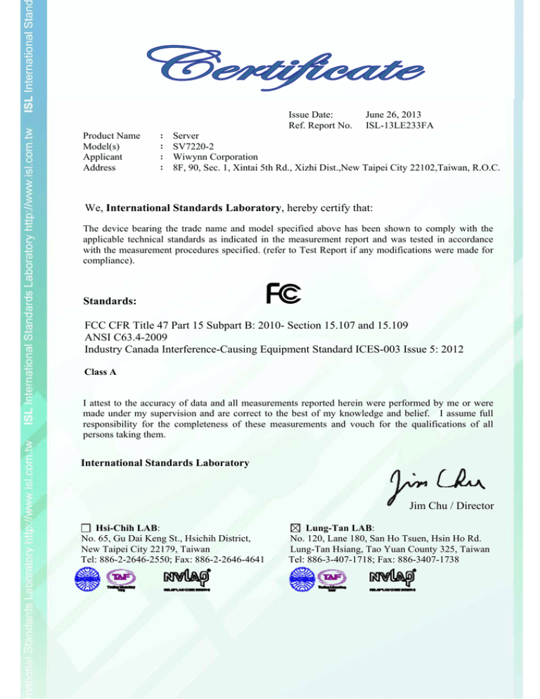
Issue Date: Ref. Report No. Product Name Model(s) Applicant Address : : : : June 26, 2013 ISL-13LE233FA Server SV7220-2 Wiwynn Corporation 8F, 90, Sec. 1, Xintai 5th Rd., Xizhi Dist.,New Taipei City 22102,Taiwan, R.O.C. We, International Standards Laboratory, hereby certify that: The device bearing the trade name and model specified above has been shown to comply with the applicable technical standards as indicated in the measurement report and was tested in accordance with the measurement procedures specified. (refer to Test Report if any modifications were made for compliance). Standards: FCC CFR Title 47 Part 15 Subpart B: 2010- Section 15.107 and 15.109 ANSI C63.4-2009 Industry Canada Interference-Causing Equipment Standard ICES-003 Issue 5: 2012 Class A I attest to the accuracy of data and all measurements reported herein were performed by me or were made under my supervision and are correct to the best of my knowledge and belief. I assume full responsibility for the completeness of these measurements and vouch for the qualifications of all persons taking them. International Standards Laboratory Jim Chu / Director Hsi-Chih LAB: No. 65, Gu Dai Keng St., Hsichih District, New Taipei City 22179, Taiwan Tel: 886-2-2646-2550; Fax: 886-2-2646-4641 Lung-Tan LAB: No. 120, Lane 180, San Ho Tsuen, Hsin Ho Rd. Lung-Tan Hsiang, Tao Yuan County 325, Taiwan Tel: 886-3-407-1718; Fax: 886-3407-1738 FCC TEST REPORT of CFR 47 Part 15 Subpart B Class A Product : Server Model(s): SV7220-2 Applicant: Wiwynn Corporation Address: 8F, 90, Sec. 1, Xintai 5th Rd., Xizhi Dist., New Taipei City 22102,Taiwan, R.O.C. Test Performed by: International Standards Laboratory <Lung-Tan LAB> *Site Registration No. BSMI: SL2-IN-E-0013; SL2-R1/R2-E-0013; TAF: 0997 FCC: TW1036; IC: IC4067B-1; NEMKO: ELA 113B VCCI: <Conduction 02>C-1440, T-1676, <Conduction 03>C-2845, T-1464, <Chamber 02>R-1435, G-17, <Chamber 12>R-2598,G-16, <Chamber 14>G-211, *Address: No. 120, Lane 180, San Ho Tsuen, Hsin Ho Rd. Lung-Tan Hsiang, Tao Yuan County 325, Taiwan *Tel: 886-3-407-1718; Fax: 886-3-407-1738 Report No.: ISL-13LE233FA Issue Date : June 26, 2013 This report totally contains 26 pages including this cover page and contents page. Test results given in this report apply only to the specific sample(s) tested and are traceable to national or international standard through calibration of the equipment and evaluating measurement uncertainty herein. This test report shall not be reproduced except in full, without the written approval of International Standards Laboratory. -i- Contents of Report 1. General ..............................................................................................................1 1.1 1.2 1.3 1.4 1.5 2. Certification of Accuracy of Test Data ..............................................................................1 Description of EUT ............................................................................................................2 Description of Support Equipment .....................................................................................4 Software for Controlling Support Unit...............................................................................5 I/O Cable Condition of EUT and Support Units ................................................................6 Powerline Conducted Emissions .......................................................................7 2.1 Test Setup and Procedure ...................................................................................................7 2.1.1 2.1.2 2.1.3 2.2 2.3 3. Test Setup ..............................................................................................................................................7 Test Procedure .......................................................................................................................................7 EMI Receiver/Spectrum Analyzer Configuration (for the frequencies tested)......................................7 Conduction Test Data: Configuration 1 .............................................................................8 Test Setup Photo...............................................................................................................10 Radiated Emissions .........................................................................................12 3.1 Test Setup and Procedure .................................................................................................12 3.1.1 3.1.2 3.1.3 3.2 3.3 4. Test Setup ............................................................................................................................................12 Test Procedure .....................................................................................................................................13 Spectrum Analyzer Configuration (for the frequencies tested) ...........................................................13 Radiation Test Data: Configuration 1...............................................................................14 Test Setup Photo...............................................................................................................18 Appendix .........................................................................................................20 4.1 4.2 4.3 Appendix A: Warning Labels...........................................................................................20 Appendix B: Warning Statement......................................................................................21 Appendix C: Test Equipment ...........................................................................................22 4.3.1 4.3.2 4.4 Test Equipment List.............................................................................................................................22 Software for Controlling Spectrum/Receiver and Calculating Test Data............................................23 Appendix D: Uncertainty of Measurement ......................................................................24 International Standards Laboratory Report Number: ISL-13LE233FA -1- 1. General 1.1 Certification of Accuracy of Test Data Standards: FCC CFR Title 47 Part 15 Subpart B: 2010- Section 15.107 and 15.109 ANSI C63.4-2009 Industry Canada Interference-Causing Equipment Standard ICES-003 Issue 5: 2012 Equipment Tested: Server Model: SV7220-2 Applicant: Wiwynn Corporation Sample received Date: June 13, 2013 Final test Date: refer to the date of test data Test Site: International Standards Laboratory Chamber 12 Test Distance: 10M; 3M (above1GHz) Temperature: refer to each site test data Humidity: refer to each site test data Input power: Conduction input power: AC 120 V / 60 Hz Radiation input power: AC 120 V / 60 Hz Test Result: PASS Report Engineer: Elly Duan Test Engineer: ______________________ Benson Chen Approved By: --------------------------------------Jim Chu / Director International Standards Laboratory Report Number: ISL-13LE233FA -21.2 Description of EUT EUT Description: Condition: Regulatory Model: CPU Pin: Server Pre-Production SV7220-2 2011Pin The devices can be installed inside the EUT are listed below: Features Specifications Mother Board 11008 CPU Intel 2.6G Memory Samsung 8GB/1333 (Model: M393B1K70DH0-YH908) 3.5“ HDD WD 250GB, SATA 3Gb/s, 7200RPM (Model: WD2502ABYS-02B7A0) PCIe Card Intel 10GbE (Model: X520-DA2) (Fiber Port*2) RAID Card LSI MegaRAID (Model: SAS 9280-8e) (Mini SAS Port*2) Mezzine Card Mellanox ConnectX-3 10GbE (Model: CX342A) (Fiber Port*2) The I/O ports of EUT are listed below: I/O Port Type LAN Port (10/100/1000Mbps) International Standards Laboratory Quantity 1 Report Number: ISL-13LE233FA -3- All the devices listed below are chosen by the applicant to be the representative configuration for testing in this report. Test Configuration: Configuration 1 Mother Board 11008 CPU Intel 2.6G *2 Memory Samsung 8GB/1333 (Model: M393B1K70DH0-YH908) *16 Power Supply Type Delta (Model: AHF-1DC-700W) Hard Disk Driver WD 250GB (Model: WD2502ABYS-02B7A0) PCIe Card Intel 10GbE (Model: X520-DA2) RAID Card LSI MegaRAID (Model: SAS 9200-8e) Mezzine Card Mellanox ConnectX-3 10GbE (Model: CX342A) Rack Delta (Model: V1 OPEN RACK) EMI Noise Source: Crystal Point 25MHz X1 32.768KHz X2 25MHz X3 48MHz X4 25MHz X5 48MHz OSC1 EMI Solution: N/A International Standards Laboratory Report Number: ISL-13LE233FA -41.3 Description of Support Equipment No Unit Model / Serial No. Brand Power Cord FCC ID 1 DELL Notebook Personal Computer Latitude D620 S/N: N/A DELL Non-shielded FCC DOC 2 Storage ST7110-30A S/N: N/A Wiwynn Non-shielded FCC DOC 3 Rack V1 OPEN RACK Delta N/A 4 PSU AHF-1DC-700W Delta Non-shielded International Standards Laboratory FCC DOC Report Number: ISL-13LE233FA -51.4 Software for Controlling Support Unit Test programs exercising various part of EUT were used. follows: 1. 2. 3. 4. 5. The programs were executed as Read and write data through EUT hard disk. Read and write data through EUT RAID Card Mini SAS Port to Storage Mini SAS Port. Receive and transmit package of EUT PCIe Fiber Port to the EUT Mezzine Card Fiber Port. Receive and transmit package of EUT to the NB through LAN port. Repeat the above steps. LAN Hard Disk Case PCIe Card Mezzine Card RAID Card International Standards Laboratory File Ping.exe EMC.exe Ping.exe Ping.exe EMC.exe Issue Date 2000/09/04 2000/09/04 Report Number: ISL-13LE233FA -61.5 I/O Cable Condition of EUT and Support Units Description Path Cable Length Cable Type Connector Type AC Power Cable 100~240V to EUT SPS 1.8M Non-shielded Plastic Head LAN Data Cable NB LAN(RJ-45) Port to EUT LAN port 33 feet Non-shielded RJ-45, Plastic Head Data Cable*2 EUT RAID Card Mini SAS Port to Storage Mini SAS Port 1.1M Shielded Metal Head Data Cable*2 EUT PCIe Fiber Port to the EUT Mezzine Card Fiber Port 3.1M Shielded Metal Head International Standards Laboratory Report Number: ISL-13LE233FA -7- 2. Powerline Conducted Emissions 2.1 Test Setup and Procedure 2.1.1 Test Setup 2.1.2 Test Procedure The measurements are performed in a 3.5m x 3.4m x 2.5m shielded room, which referred as Conduction 01 test site, or a 3m x 3m x 2.3m test site, which referred as Conduction 02 test site. The EUT was placed on non-conduction 1.0m x 1.5m table, which is 0.8 meters above an earth-grounded. Power to the EUT was provided through the LISN which has the Impedance (50ohm/50uH) vs. Frequency Characteristic in accordance with the standard. Power to the LISNs were filtered to eliminate ambient signal interference and these filters were bonded to the ground plane. Peripheral equipment required to provide a functional system (support equipment) for EUT testing was powered from the second LISN through a ganged, metal power outlet box which is bonded to the ground plane at the LISN. The interconnecting cables were arranged and moved to get the maximum measurement. Both the line of power cord, hot and neutral, were measured. All of the interface cables were manipulated according to ANSI C63.4 requirements. The highest emissions were analyzed in details by operating the spectrum analyzer in fixed tuned mode to determine the nature of the emissions and to provide information which could be useful in reducing their amplitude. 2.1.3 EMI Receiver/Spectrum Analyzer Configuration (for the frequencies tested) Frequency Range: Detector Function: Resolution Bandwidth: International Standards Laboratory 150KHz~30MHz Quasi-Peak / Average Mode 9KHz Report Number: ISL-13LE233FA -82.2 Conduction Test Data: Configuration 1 Table 2.2.1 Power Line Conducted Emissions (Line) Note: Margin = QP/AVG Emission - Limit QP/AVG Emission = Receiver Reading + Correct Factor Correct Factor = LISN Loss + Cable Loss A margin of -8dB means that the emission is 8dB below the limit The frequency spectrum graph is for final peak graph, and the attached table is for QP/AVG test result. If peak data can pass, it will be shown in “QP/AVG Correct” column, if not, QP/AVG data will instead. The CISPR 22 limits would be applied to all FCC Part 15 devices. International Standards Laboratory Report Number: ISL-13LE233FA -9Table 2.2.2 Power Line Conducted Emissions (Neutral) Note: Margin = QP/AVG Emission - Limit QP/AVG Emission = Receiver Reading + Correct Factor Correct Factor = LISN Loss + Cable Loss A margin of -8dB means that the emission is 8dB below the limit The frequency spectrum graph is for final peak graph, and the attached table is for QP/AVG test result. If peak data can pass, it will be shown in “QP/AVG Correct” column, if not, QP/AVG data will instead. The CISPR 22 limits would be applied to all FCC Part 15 devices. International Standards Laboratory Report Number: ISL-13LE233FA -102.3 Test Setup Photo Front View International Standards Laboratory Report Number: ISL-13LE233FA -11- Back View International Standards Laboratory Report Number: ISL-13LE233FA -12- 3. Radiated Emissions 3.1 Test Setup and Procedure 3.1.1 Test Setup International Standards Laboratory Report Number: ISL-13LE233FA -13- 3.1.2 Test Procedure The radiated emissions test will then be repeated on the open site or chamber to measure the amplitudes accurately and without the multiple reflections existing in the shielded room. The EUT and support equipment are set up on the turntable of one of 10 meter open field sites or 10 meter chamber. Desktop EUT are set up on a wooden stand 0.8 meter above the ground or floor-standing arrangement shall be placed on the horizontal ground reference plane. The test volume for a height of up to 30 cm may be obstructed by absorber placed on the ground plane. For the initial measurements, the receiving antenna is varied from 1-4 meter height and is changed in the vertical plane from vertical to horizontal polarization at each frequency. The highest emissions between 30 MHz to 1000 MHz were analyzed in details by operating the spectrum analyzer and/or EMI receiver in quasi-peak mode to determine the precise amplitude of the emissions. The highest emissions between 1 GHz to 40 GHz were analyzed in details by operating the spectrum analyzer in peak and average mode to determine the precise amplitude of the emissions. Place the measurement antenna away from each area of the EUT determined to be a source of emissions at the specified measurement distance, while keeping the antenna in the cone of radiation from that area and pointed at the area both in azimuth and elevation, with polarization oriented for maximum response. At the highest amplitudes observed, the EUT is rotated in the horizontal plane while changing the antenna polarization in the vertical plane to maximize the reading. The interconnecting cables were arranged and moved to get the maximum measurement. Once the maximum reading is obtained, the antenna elevation and polarization will be varied between specified limits to maximize the readings. All of the interface cables were manipulated according to ANSI C63.4 requirements. The highest internal source of the EUT is defined as the highest frequency generated or used within the EUT or on which the EUT operates or tunes. If the highest frequency of the internal sources of the EUT is less than 108 MHz, the measurement shall only be made up to 1 GHz. If the highest frequency of the internal sources of the EUT is between 108 MHz and 500 MHz, the measurement shall only be made up to 2 GHz. If the highest frequency of the internal sources of the EUT is between 500 MHz and 1 GHz, the measurement shall only be made up to 5 GHz. If the highest frequency of the internal sources of the EUT is above 1 GHz, the measurement shall be made up to 5 times the highest frequency or 40 GHz, whichever is less. Spectrum Analyzer Configuration (for the frequencies tested). 3.1.3 Spectrum Analyzer Configuration (for the frequencies tested) Frequency Range: Detector Function: Resolution Bandwidth: 30MHz--1000MHz Quasi-Peak Mode 120KHz Frequency Range: Detector Function: Resolution Bandwidth: Above 1000MHz Peak/Average Mode 1MHz International Standards Laboratory Report Number: ISL-13LE233FA -143.2 Radiation Test Data: Configuration 1 Table 3.2.1 Radiated Emissions (Horizontal) * Note: Margin = Emission – Limit Emission = Radiated Amplitude + Correct Factor Correct Factor = Antenna Correction Factor + Cable Loss A margin of -8dB means that the emission is 8dB below the limit BILOG Antenna Distance: 10 meters The CISPR 22 limits would be applied to all FCC Part 15 devices. Below 1GHz test, if the peak measured value meets the QP limit, it is unnecessary to perform the QP measurement. measurement. International Standards Laboratory Report Number: ISL-13LE233FA -15- * Note: Margin = Emission – Limit Emission = Radiated Amplitude + Correct Factor Correct Factor = Antenna Correction Factor + Cable Loss – Pre-Amplifier Gain A margin of -8dB means that the emission is 8dB below the limit Horn Antenna Distance: 3 meters The CISPR 22 limits would be applied to all FCC Part 15 devices. Above 1GHz test, if the peak measured value meets the average limit, it is unnecessary to perform the average measurement. International Standards Laboratory Report Number: ISL-13LE233FA -16Table 3.2.2 Radiated Emissions (Vertical) * Note: Margin = Emission – Limit Emission = Radiated Amplitude + Correct Factor Correct Factor = Antenna Correction Factor + Cable Loss A margin of -8dB means that the emission is 8dB below the limit BILOG Antenna Distance: 10 meters The CISPR 22 limits would be applied to all FCC Part 15 devices. Below 1GHz test, if the peak measured value meets the QP limit, it is unnecessary to perform the QP measurement. measurement. International Standards Laboratory Report Number: ISL-13LE233FA -17- * Note: Margin = Emission – Limit Emission = Radiated Amplitude + Correct Factor Correct Factor = Antenna Correction Factor + Cable Loss – Pre-Amplifier Gain A margin of -8dB means that the emission is 8dB below the limit Horn Antenna Distance: 3 meters The CISPR 22 limits would be applied to all FCC Part 15 devices. Above 1GHz test, if the peak measured value meets the average limit, it is unnecessary to perform the average measurement. International Standards Laboratory Report Number: ISL-13LE233FA -183.3 Test Setup Photo Front View Back View International Standards Laboratory Report Number: ISL-13LE233FA -19- Front View (above 1GHz) Back View (above 1GHz) International Standards Laboratory Report Number: ISL-13LE233FA -20- 4. Appendix 4.1 Appendix A: Warning Labels Label Requirements A Class A digital device subject to certification by the FCC shall carry a warning label which includes the following statement: ***WARNING*** This device complies with Part 15 of the FCC Rules. Operation is subject to the following two conditions: (1) this device may not cause harmful interference, and (2) this device must accept any interference received, including interference that may cause undesired operation. International Standards Laboratory Report Number: ISL-13LE233FA -214.2 Appendix B: Warning Statement Statement Requirements The operators’ manual for a Class A digital device shall contain the following statements or their equivalent: ***WARNING*** This equipment has been tested and found to comply with the limits for a Class A digital device, pursuant to part 15 of the FCC Rules. These limits are designed to provide reasonable protection against harmful interference when the equipment is operated in a commercial environment This equipment generates, uses, and can radiate radio frequency energy and, if not installed and uses in accordance with the instruction manual, may cause harmful interference to radio communications Operation of this equipment in a residential area is likely to cause harmful interference in which case the user will be required to correct the interference at his own expense. Notice: The changes or modifications not expressly approved by the party responsible for compliance could void the user's authority to operate the equivalent. * * * * * * * * * If the EUT was tested with special shielded cables the operators manual for such product shall also contain the following statements or their equivalent: Shielded interface cables and/or AC power cord, if any, must be used in order to comply with the emission limits. International Standards Laboratory Report Number: ISL-13LE233FA -224.3 Appendix C: Test Equipment 4.3.1 Test Equipment List Location Chmb12 Conduction 12 Equipment Name Brand EMI Receiver 11 Conduction 12 LISN 20 Conduction 12 Conduction 03 -1 Cable ROHDE & ESCI SCHWARZ ROHDE&SCHWA ENV 216 RZ WOKEN CFD 300-NL Location Chmb12 Radiation (Chamber12) Radiation (Chamber12) Radiation (Chamber12) Equipment Name Brand BILOG Antenna 04 Coaxial Cable Chmb 12-10M-01 EMI Receiver 10 Location Chamber12 Rad. Above 1GHz Rad. Above 1GHz Rad. Above 1GHz Rad. Above 1GHz Rad. Above 1GHz S/N Last Cal. Date Next Cal. Date 100568 07/16/2012 07/16/2013 101477 05/13/2013 05/13/2014 Conduction 03 06/28/2012 -1 06/28/2013 Model S/N Last Cal. Date Next Cal. Date Schaffner CBL6112B 2764 02/25/2013 02/25/2014 PEWC CFD400-NL 06/28/2012 06/28/2013 ROHDE & SCHWARZ ESCI Chmb 12-10M-01 100567 07/20/2012 07/20/2013 Brand Model S/N Last Cal. Date Next Cal. Date Spectrum Analyzer 22 Rohde&Schwarz FSU43 100143 05/03/2013 05/03/2014 Preamplifier 19 MITEQ 09/28/2012 09/28/2013 Horn Antenna 08 ETS-Lindgren AFS44-0010180 1579008 0-25-10P-44 3117 000128602 09/28/2012 09/28/2013 Microwave Cable-01_2010 Microwave Cable-08 HUBER SUHNER SUCOFLEX 102 HUBER SUHNER SUCOFLEX 102 35145/2 09/27/2012 09/27/2013 35633/2 09/27/2012 09/27/2013 Equipment Name International Standards Laboratory Model Report Number: ISL-13LE233FA -234.3.2 Software for Controlling Spectrum/Receiver and Calculating Test Data Site Filename Version Issue Date Conduction/Radiation EZ EMC ISL-03A2 3/6/2013 International Standards Laboratory Report Number: ISL-13LE233FA -244.4 Appendix D: Uncertainty of Measurement The measurement uncertainty refers to CISPR 16-4-2:2003. The coverage factor k = 2 yields approximately a 95 % level of confidence. <Conduction 03> AMN: ±3.29dB ISN: ±4.43dB <Chamber 12 (10M)> Horizontal 30MHz~200MHz: 200MHz~1000MHz: Vertical 30MHz~200MHz: 200MHz~1000MHz: ±4.26dB ±4.38dB ±4.52dB ±4.38dB <Chamber 12 (3M)> 1GHz~6GHz: ±4.63dB 6GHz~18GHz: ±5.33dB International Standards Laboratory Report Number: ISL-13LE233FA
