THIS DRAWING HAS BEEN GENERATED
AND IS MAINTAINED BY A CAD SYSTEM.
CHANGES SHALL ONLY BE
INCORPORATED AS DIRECTED BY THE
DESIGN ACTIVITY.
DRAWN:
UNLESS
OTHERWISE
SPECIFIED DIM.
IN INCHES
BEFORE
PLATING
LTR
DESCRIPTION
ECO NUM.
DATE
APPROVED
C
WIRE LENGTH 18” TO 16” +
4554
5/24/02
MLH
D
HAZARDOUS LOCATIONS
CERTIFICATION –
CLASS 1 DIV 2 APPROVAL
8689
3/15/10
MPD
E
ON SHT 3 ADDED 4.2.1
12268
12/19/13
MTH
F
REMOVE OBSOLETE REF
12313
1/20/14
MTH
MLH
DATE
10/01/01
MWG
10/18/01
CHECKED:
ENGR. APPD:
DE
10/19/01
TITLE:
PROJ. APPD:
MLH
MATERIAL:
REVISIONS
Product Specification
10/19/01
PDS Series
APPROVED:
NOTICE:
THE INFORMATION
AND DESIGN CONTAINED HEREIN IS
THE PROPERTY OF TRANSTECTOR
SYSTEMS. WHO RESERVES ALL
RIGHTS THERETO
SIZE
CAGE
A
30992
SCALE = N/A
DRAWING NUMBER
REV
1400-404
PAGE 1 OF 3
F
SUPPRESSOR PERFORMANCE SPECIFICATION
PDS-1 (1101-586)
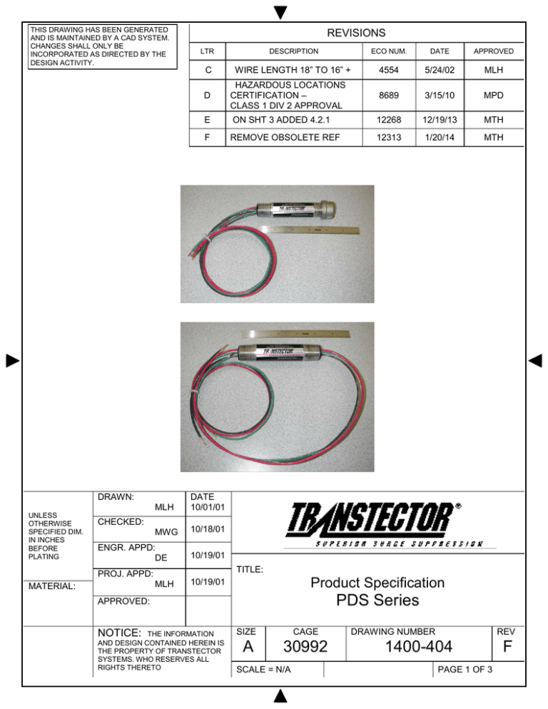
1. GENERAL DESCRIPTION: The PDS Series Pipe Data surge suppressors are high-speed,
high-current, solid-state devices designed to protect electronic equipment and systems from
transient overvoltages. The suppressor limits the magnitude of transient overvoltages that
may occur on low voltage DC power lines, 4-20mA current loops or low frequency data lines.
Systems where the PDS Series have been installed include:
The PDS Series surge suppressors are hybrid technology designed products that utilize
silicon avalanche suppression diodes (SASD) for the primary protection and Gas Discharge
Tubes (GDT) for secondary or backup protection. The SASD suppressor provides
continuous, bipolar protection and automatically resets after a surge event with no
degradation to its protection capabilities.
The suppressors are intended to be installed anywhere power or communication lines are run
through ½” schedule pipe. The PDS-1 suppressor provides the input and output wires on one
end, allowing for a T connector system installation. The PDS-2 provides the input and output
wires on opposite ends, allowing for a straight in-line system installation. The PDS Series
connect via 18AWG wire.
Note: The PDS surge suppressors REQUIRE a low impedance path to Earth ground.
The PDS-1 and PDS-2 surge suppressors are approved for hazardous locations that require
a rating of Class1 Division 2, Groups A, B, C, D.
2. ELECTRICAL SERVICE:
2.1.
2.2.
2.3.
2.4.
2.5.
2.6.
Input/Output Connection .......................................................... 16”+ length 18AWG Wires
Configuration ................................................................................................... 2 pair/4 wire
Protection Modes ................................................................................................Line-GND
Pass-Through Current (Max.) ...................................................................................... 10A
Maximum Continuous Operating Voltage ............................................................... 13VDC
Capacitance ............................................................................................. < 8pF L-L, L-G
3. ELECTRICAL PERFORMANCE:
3.1. Response Time (All Models) ........................................................... 5 nanoseconds (Max.)
3.2. Gas Discharge Tube ratings
3.2.1.Vbr ....................................................................................~90Vpk @ 5mADC L-L, L-G
3.2.2.Vpl ................................................................................ 20kV / 10kA (8x20us) L-L, L-G
3.3. SASD suppressor ratings
3.3.1.Vbr ....................................................................................~35Vpk @ 5mADC L-L, L-G
3.3.2.Vpl ....................................................................125Vp @ 6kV / 3kA (8x20us) L-L, L-G
3.3.3.Vpl ................................................................250Vp @ 20kV / 10kA (8x20us) L-L, L-G
3.3.4.Vpl .....................................................................250Vp @ 100A (10x1000us) L-L, L-G
NOTICE: THE
INFORMATION
AND DESIGN CONTAINED HEREIN
IS THE PROPERTY OF
TRANSTECTOR SYSTEMS. WHO
RESERVES ALL RIGHTS THERETO.
SIZE
CAGE
A 30992
SCALE = N/A
1400-404
F
Page 2 OF 3
4. CERTIFICATIONS:
4.1. Meet requirements of UL 497b and Belcore GR1089
4.2. Hazardous Locations; FM Approvals Class I Division 2 US, Canada and EU
4.2.1. INSTALLATION When installed as category 3 equipment the PDS Series surge
suppressor shall be mounted within a tool secure enclosure which meets the
requirements of EN 60079-0 and EN 60079-15 and is capable of accepting the
applicable wiring methods specified in EN 60079-14 . When installed in outdoor or
potentially wet locations, the enclosure shall, at a minimum, meet the requirements
of IP54. When installed in locations providing adequate protection against the entry
of solid foreign objects or water capable of impairing safety, the enclosure shall, at
a minimum, meet the requirements of IP4X. The final enclosure shall not contain
more than 7.5% in total magnesium.
4.3. Labeling Requirements
4.3.1.Main Product Label
Transtector
10701 Airport Drive, Hayden ID 83835
PDS-1 1101-586
AEx/Ex nA IIC T4 Tamb = -40°C to +65°C
Class 1, Division 2, Groups A, B, C, D;
T4A Tamb = -40°C to +65°C
II 3 G Ex nA IIC
T4 Tamb = -40°C to +65°C
FM10ATEX0002X.
4.3.2.Secondary Label
Serial Number
Date Code (year of construction)
5. ENVIRONMENTAL:
5.1. Storage/Operating Temperature: ............................................................... -40C to +65C
5.2. Relative Humidity ........................................................................................................ 95%
6. MECHANICAL:
6.1.
6.2.
6.3.
6.4.
Dimensions ............................................................................................ ½” Diameter x 6” L
Material ...................................................................................Schedule 40 Stainless Steel
Threads .......................................................................................... ½” NPT threaded ends
Weight (Max.) ............................................................................................................. 2 Oz.
Note: Green Ground wire must be connected to a solid earth ground for proper suppressor
operation.
© 2015 T r a n s t e c t o r. All rights reserved
NOTICE: THE
INFORMATION
AND DESIGN CONTAINED HEREIN
IS THE PROPERTY OF
TRANSTECTOR SYSTEMS. WHO
RESERVES ALL RIGHTS THERETO.
SIZE
CAGE
A 30992
SCALE = N/A
1400-404
F
Page 3 OF 3

