SeaBlazeX Instructions Card Insert Front 1.0 (for
advertisement

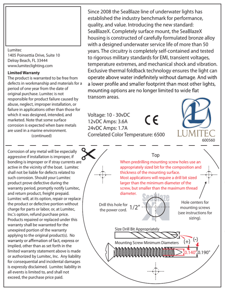
Lumitec 1405 Poinsettia Drive, Suite 10 Delray Beach, FL 33444 www.lumiteclighting.com Limited Warranty The product is warranted to be free from defects in workmanship and materials for a period of one year from the date of original purchase. Lumitec is not responsible for product failure caused by abuse, neglect, improper installation, or failure in applications other than those for which it was designed, intended, and marketed. Note that some surface corrosion is expected when bare metals are used in a marine environment. (continued) Corrosion of any metal will be especially aggressive if installation is improper, if bonding is improper or if stray currents are active in the vicinity of the boat. Lumitec shall not be liable for defects related to such corrosion. Should your Lumitec product prove defective during the warranty period, promptly notify Lumitec, and return product, freight prepaid. Lumitec will, at its option, repair or replace the product or defective portion without charge for parts or labor, or, at Lumitec, Inc.'s option, refund purchase price. Products repaired or replaced under this warranty shall be warranted for the unexpired portion of the warranty applying to the original product(s). No implied, other than as set forth in the limited warranty statement above is made or authorized by Lumitec, Inc. Any liability for consequential and incidental damages is expressly disclaimed. Lumitec liability in all events is limited to, and shall not exceed, the purchase price paid. Since 2008 the SeaBlaze line of underwater lights has established the industry benchmark for performance, quality, and value. Introducing the new standard: SeaBlazeX. Completely surface mount, the SeaBlazeX housing is constructed of carefully formulated bronze alloy with a designed underwater service life of more than 50 years. The circuitry is completely self-contained and tested to rigorous military standards for EMI, transient voltages, temperature extremes, and mechanical shock and vibration. Exclusive thermal foldback technology ensures the light can transom areas. Voltage: 10 - 30vDC 12vDC Amps: 3.6A 24vDC Amps: 1.7A Correlated Color Temperature: 6500 600560 Top When predrilling mounting screw holes use an appropriately sized bit for the composition and thickness of the mounting surface. Most applications will require a drill bit sized larger than the minimum diameter of the screw, but smaller than the maximum thread diameter. Drill this hole for the power cord. 1/2” Hole centers for mounting screws (see instructions for sizing). Size Drill Bit Appropriately Mounting Screw Minimum Diameters 0.140" 0.190" Note: • Because of the innovative radially asymmetrical beam output of your SeaBlazeX lights, ORIENTATION IS VERY IMPORTANT! Lights should be mounted with the logo in an upright position so that the widebeam pattern fans out to illuminate the water surface. • Lights must be operated on an appropriately fused or circuit breaker protected circuit. • Lights are not recommended for mounting on running surfaces (e.g., the bottom surface of a hull) • For best performance, lights should be mounted below the waterline • Bottom paint is not required, however lights can be painted with any bronze-safe paint if desired. Mounting Location: light will not interfere with the operation of engines, trim tabs, rudders, etc. Ideal mounting locations include transoms, the side and back surfaces of engine brackets, and the undersides of dive platforms. For maximum performance SeaBlazeX lights should be mounted 6” to 16” below the waterline. Installation at depths greater than 36” is not recommended. Mounting your SeaBlazeX light: Tape the mounting template in the desired mounting location. Drill holes for the mounting screws and wire boss as indicated on the mounting template. NOTE! The mounting screws provided with your SeaBlazeX light, while very corrosion resistant, are softer than typical steel screws. Extreme care must be taken when driving screws to prevent screw heads from shearing off. The diameter of the pilot hole required for the mounting screws will depend largely on the composition and thickness of the mounting surface. • Size pilot holes so that only moderate torque is needed to drive the screw into the mounting surface. Typically this hole size will be slightly smaller than the outside diameter of the widest threads. Test the size of the mounting hole prior to installation. Carefully turn screws to avoid breaking them. If screw is too tight, back out and re-size screw hole. When • Thoroughly coat the back surface of the SeaBlazeX light with a marine-grade sealant designed for below-waterline applications. Dab additional sealant on the holes in the mounting surface, forcing some sealant into the holes. Extreme care should be taken to properly seal the through-hull (wire) hole to prevent water intrusion. boat to help it feed through the hole. Tighten the mounting screws evenly. Sealant should be forced from all sides as the hole to properly seal and prevent water intrusion. Allow the sealant to cure thoroughly per the manufacturer’s instructions prior to returning the vessel to the water. Note: Any time a hole is bored into a vessel’s hull (for example mounting screws for transducers, dive platforms, throughthe through-hull hole is thoroughly sealed on both sides of the hull. Additionally, the back (inside) surface where the wire exits the through-hull hole should be carefully sealed using the wire strain relief. Operation: An abrupt OFF/ON toggle of your standard (SPST) switch allows the SeaBlazeX (single and dual color models) to transition through various light output modes. Single Color Light Output Modes: 1 – Constant 2 – Fade 3 – Flashing/strobe Dual Color Light Output Modes: 1 – Cross-Color Fade – gently undulating color mix 2 – On, White 3 – On, Blue 4 – On, White and Blue 5 – Flashing, two color • Lumitec, Inc. assumes no responsibility whatsoever for any damage, loss, or injury that may result from the incorrect installation of this product, including but not limited to the vessel sinking, structural damage due to water intrusion, electrical malfunction, etc. • Light circuits should be protected with an appropriately sized fuse. Each light draws approximately 3.7A at 12VDC and 1.7A at 24VDC. Fuses on circuits with multiple lights should be sized accordingly.


