Inorganic LCD Technology
Technology Guide
Introduction
Liquid-crystal display (LCD) technology has come a long way from
its humble beginnings back in the early 1970’s when it first appeared
in calculators and digital watches. Today, it has blossomed into the
dominant technology for all manner of displays, from mobile phones
and digital cameras to desktop monitors and high-definition televisions.
In a variant known as high-temperature poly-silicon (HTPS) LCD is also
the most popular technology for digital projectors. Projection is a more
challenging application for a liquid-crystal device than a direct-view
display. In order to project a bright image most digital projectors use
a short-arc, high-intensity discharge lamp based on Mercury vapor
or Xenon as their internal light source. Historically, achieving the right
balance between high brightness and high contrast with these lamps
has been tricky.
To make a device capable of displaying an image, the electrical
conductors coating the glass plates are divided into a rectangular array
of pixels, which are addressed using row and column electrodes. When
one row and one column electrode are energized, a thin-film transistor
(TFT) at the selected pixel is turned on to control the intensity of light
passing through the pixel (Figure 2).
In an LCD projector, three devices are used to form a full-color image,
one for modulating red light, one for green light and a third for blue
light. Some LCD projectors make use a fourth device to improve color
saturation and light output (e.g., Christie’s 4DColor™ technology).
However, that all changed with the development of inorganic LCD
technology. This brief explains what it is, how it works and the benefits
it brings to LCD projection applications.
LCD Basics
First, let’s briefly review the construction and theory of operation of
an LCD. The core element of an LCD is, of course, the liquid crystal
material itself. This is a substance that flows like a liquid yet behaves like
a crystal in the sense that its molecules can be oriented in an orderly
structure under the right conditions.
In this case, the right conditions include the application of an electric
field. In an LCD, the liquid crystal material is sandwiched between
two thin, glass plates coated with a transparent electrical conductor.
Application of a voltage across the plates causes a change in the
orientation of the liquid-crystal molecules, which have a rod-like shape.
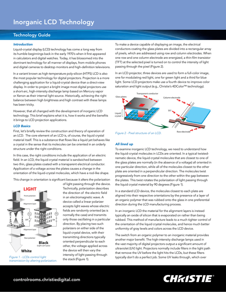
This change in orientation is significant because it alters the polarization
of light passing through the device.
Technically, polarization describes
the direction of the electric field
in an electromagnetic wave. A
device called a linear polarizer
accepts light waves whose electric
fields are randomly oriented (as is
normally the case) and transmits
only those oscillating in a particular
direction. By placing two such
polarizers on either side of the
liquid-crystal device, with their
transmitting directions typically
oriented perpendicular to each
other, the voltage applied across
the device will then vary the
intensity of light passing through
Figure 1 - LCDs control light
the
stack (Figure 1).
transmission by altering polarization.
controlrooms.christiedigital.com
Figure 2 - Pixel structure of an LCD.
All lined up
To examine inorganic LCD technology, we need to understand how
the liquid-crystal molecules in LCDs are oriented. In a typical twistednematic device, the liquid crystal molecules that are closest to one of
the glass plates are normally (in the absence of a voltage) all oriented in
one particular direction, while all of the molecules closest to the other
plate are oriented in a perpendicular direction. The molecules twist
progressively from one direction to the other within the gap between
the plates. This twist rotates the polarization of light passing through
the liquid crystal material by 90 degrees (Figure 1).
In a standard LCD device, the molecules closest to each plate are
aligned into their respective orientations by the presence of a layer of
an organic polymer that was rubbed onto the glass in one preferential
direction during the LCD manufacturing process.
In an inorganic LCD the material for the alignment layers is instead
typically an oxide of silicon that is evaporated on rather than being
rubbed. This method of manufacture leads to a much tighter control of
the orientation of the liquid crystal molecules, and hence much better
uniformity of gray levels and colors across the LCD device.
The switch from an organic polymer to an inorganic material provides
another major benefit. The high-intensity discharge lamps used in
the vast majority of digital projectors output a significant amount of
ultraviolet (UV) light. Projectors normally include filters in the light path
that remove the UV before the light hits the LCDs, but these filters
typically don’t do a perfect job. Some UV leaks through, which over
Inorganic LCD Technology
Technology Guide
time can literally “cook” the organic molecules of a polymer alignment
layer, breaking down their molecular cohesion.
An inorganic alignment layer does not absorb as much UV and hence
is significantly more resistant to UV-induced damage. This translates
directly into a much higher device reliability and the ability to withstand
much higher levels of light.
Standing Tall
A pixel of a typical twisted-nematic LCD device normally appears white
when no voltage is applied across the glass plates. In the presence
of a voltage the liquid crystal molecules start to “untwist,” rotating
the polarization by less than 90 degrees, which results in less light
transmitted through the pixel. At some voltage the molecules align in a
vertical direction and the pixel blocks as much light as it can, producing
as deep a black as possible. (Figure 3).
Figure 4 - The vertically aligned liquid crystal of an inorganic panels is
normally black.
the use of inorganic alignment layers with their extremely uniform
characteristics ensures that the molecules are all accurately aligned in
the vertical direction with little variation, which reduces scattering and
the resultant light leakage to a minimum.
The Benefits
Inorganic alignment technology and the “vertically aligned” (normally
black) mode of operation that comes with it provide powerful benefits
to LCD projection applications.
Figure 3 - A standard twisted nematic LCD normally displays white.
Unfortunately, because of natural variations not all molecules align
precisely vertical. This increases scattering, which lets some light leak
through. Because of this effect, the black levels traditionally achieved
by LCDs have not been as dark as those achieved by other projection
technologies such as LCoS (Liquid Crystal on Silicon) and DLP®.
However, the use of inorganic alignment layers allows an entirely
different mode of operation. In this mode, the rod-like liquid crystal
molecules are all aligned vertically in the absence of a voltage. This
makes the display normally black instead of normally white. Application
of a voltage then starts to twist the molecules, allowing more light
through as the voltage increases (Figure 4).
The most visible benefit is a vastly improved contrast ratio, due to the
achievement of a far deeper black than would otherwise be possible.
This improves the readability of fine text and graphics and adds
“punch” to video material, especially in darker scenes. Less obviously, it
makes colors far more vibrant, particularly darker tones closer to black.
Another immediately visible benefit is the increase in light output that
inorganic alignment layers allow by virtue of their greatly improved
resistance to damage from UV light. More light means brighter images
that withstand higher levels of ambient illumination, making projection a
viable display option in a wider variety of environments.
Improved resistance to UV light also results in higher reliability.
Practically speaking, it means you no longer have to worry about the
number of cumulative hours that an LCD projector has been operating.
In short, inorganic LCD technology enables brighter images, deeper
blacks and higher reliability – a winning combination.
The normally black mode allows a far deeper black to be produced.
Not only does the black state not depend on an analog voltage, but
Independent sales
consultant offices
Corporate offices
Worldwide offices
Christie Digital Systems USA, Inc
USA – Cypress
ph: 714 236 8610
United Kingdom
ph: +44 (0) 118 977 8000
United Arab Emirates
ph: +971 (0) 4 299 7575
China (Beijing)
ph: +86 10 6561 0240
Spain
ph: +34 91 633 9990
Germany
ph: +49 2161 664540
India
ph: (080) 41468941 – 48
Japan (Tokyo)
ph: 81 3 3599 7481
Italy
ph: +39 (0) 2 9902 1161
France
ph: +33 (0) 1 41 21 44 04
Singapore
ph: +65 6877 8737
Korea (Seoul)
ph: +82 2 702 1601
South Africa
ph: +27 (0) 317 671 347
Eastern Europe and
Russian Federation
ph: +36 (0) 1 47 48 100
China (Shanghai)
ph: +86 21 6278 7708
Christie Digital Systems Canada, Inc.
Canada – Kitchener
ph: 519 744 8005
For the most current specification information, please visit http://www.christiedigital.com
Copyright 2010 Christie Digital Systems USA, Inc. All rights reserved. All brand names and product names are trademarks, registered trademarks
or tradenames of their respective holders. Canadian manufacturing facility is ISO 9001 and 14001 certified. Performance specifications are typical.
Due to constant research, specifications are subject to change without notice. Inorganic Technical Guide April 10


