3.5” QVGA 16.7M color TFT LCD module
with Touch Panel integrated
TechToys Company
www.TechToys.com.hk
Version 31122008
All Rights Reserved
Written by: John Leung
INTRODUCTION
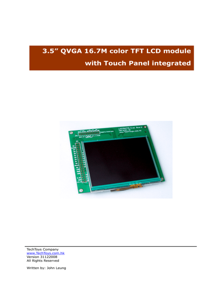
The part number LVC75Z779 Eval Board (Version 1E) is a development board for
3.5” 16.7m color QVGA TFT-LCD module with Touch Panel integrated. It is completed
with an external image processor Solomon SSD1928, microSD card connector, header for
CMOS camera module, and backlight driving circuit. Standardized footprint for 2.54mm
PCB header is provided to allow you to do prototype in a handy way. SSD1928 is able to
interface with different type of generic microcontrollers as low as an 8-bit, low-pin-count
microcontroller without paying much attention to generation of timing signals that are
required to drive larger LCD displays. On top, there are the hardware JPEG codec and
camera interface built-in the image processor which make this development board ideal
for design of hand-held Digital Photo Viewer, GPS, PDA, and a lot more small-sized
control devices.
Below please find an illustration of all components in details.
J2: 0.5mmPitch SMT
Bottom contact FPC
LT1937 backlight
driving circuit
Dip switch for 8-bit
or 16-bit addressing
JP1: footprint for 2x20
2.54mm receptacle/header
for host control (mcu)
JP2: 2x12 2.00mm
receptacle/header for
camera input
SSD1928 Image Processor
TechToys Company
www.TechToys.com.hk
Version 31122008
All Rights Reserved
Written by: John Leung
microSD Connector
INSTALLATION
The flat cable connector J2 is a bottom contact type. Please make sure the signal
contacts of the LCD module are facing down the connector as shown in Figure 1 and you
are using the least force to open the connector in the proper direction.
Figure 1
Signal contacts of LCD module face down for J2 FPC
JP1 provides a footprint for 2x20 2.54mm header for host microcontroller connection.
There are two orientations to use the kit:
1. Component face up leaving LCD module’s flat cable straight (Figure 1)
2. Component face down with LCD flipped over (Figure 2)
Figure 2
TechToys Company
www.TechToys.com.hk
Version 31122008
All Rights Reserved
Written by: John Leung
LCD flipped over bottom side of PCB
Orientation 1 (Figure 1) offers the flexibility to expose all test points onboard for
hardware debug. Look closely J2 FPC, you will find all test points for LCD module
including LCD_RST, LCD_D0~D7, LCD_CLK, VSYNC, HSYNC, etc. These 1mm-diameter
gold plates offer convenient test points for DSO probe. It is like everything is put on
table for hardware development.
Orientation 21 (Figure 2) offers a plug-n-play method for stacking with our development
boards such as the ARM LPC2103 evaluation board, PIC18LF4550 board, and PIC24
evaluation board. With a 2x20 2.54mm receptacle soldered to the component side of the
PCB, one may use our evaluation boards for immediate compatibility and example code
for out-of-the-box evaluation.
Figure 3 below shows how LVC75Z779 Eval Board is stacked on PIC18LF4550 evaluation
board. A CMOS camera module also installed for illustration purpose.
Figure 3
1
LVC75Z779 Eval Board stacks with
PIC18LF4550 Eval Board
Pay attention to insulation of LCD’s metallic enclosure to bottom side of the PCB
TechToys Company
www.TechToys.com.hk
Version 31122008
All Rights Reserved
Written by: John Leung
Before leaving this section, it is important to mention that there is a footprint for 1x20
2.54mm receptacle near the right edge of the PCB. This receptacle does not provide any
connection to any of the components. It is just for keeping the PCB in a nicely horizontal
position thus it is optional.
However, after all headers got soldered, one must use a plastic sheet to cover the PCB
(or covering the metallic enclosure of the LCD module) to avoid short-circuit between
vias and the metallic enclosure.
1x20 receptacle
footprint for support
A plastic sheet is
required for insulation
Figure 4
A plastic sheet is required to cover the bottom PCB to
avoid short-circuit between vias of PCB to the metallic enclosure of
LCD module.
TechToys Company
www.TechToys.com.hk
Version 31122008
All Rights Reserved
Written by: John Leung
FEATURES
There are various solutions to drive a LCD module, two of them are described in
Microchip’s web site at this address
http://www.microchip.com/stellent/idcplg?IdcService=SS_GET_PAGE&nodeId=2608&param=en533860
Built-in controller is usually for smaller display (less than 3”). For panel larger than 3.5”,
external graphic controller is required.
External graphic/LCD controllers relieve the microcontroller from graphics manipulation
and image rendering. Some of the controllers not only give you basic LCD panel interface,
but also equipped with more advanced features such as double buffer for multi-pages
and instantaneous screen update, Picture-in-Picture support, and JPEG codec, just to
mention few of them. There are a number of famous manufacturers of such external
controller for example, Epson, Himax, Solomon-Systech Ltd. Our board uses SSD1928
Image Processor of Solomon-Systech for the following features.
The LCD controller of SSD1928 supports digital LCD panels with configurable timing
signals VSYNC, HSYNC, and PCLK or DOTCLK
Camera input for still picture capture and image preview in form of a life video
Hardware JPEG codec to encode and decode JPEG images. This feature evolves the
consumer market of Digital Photo Viewer and Handheld GPS by opening the gate for
low-end microcontrollers (e.g. 8-bit microcontrollers) to interface with LCD panels of
size 3 inches or larger. It is because such panels usually require timing signals which
are not built-in with most low-end microcontrollers. Furthermore, JPEG files require
complicated algorithm to decompress and decode headers and tables to extract pixel
information for LCD panel. Software encode and decode libraries are not needed
because these would be handled by hardware of SSD1928
Files can be saved into SD/MMC card through SD interface. The JPEG file is retrieved
back from SD/MMC card, decoded and displayed on LCD panel
Support various interface types, including 8-bit or 16-bit 8080 indirect addressing
(e.g. Microchip PIC18/24/32, ATMEL AVR-series, 8051, etc.), SRAM interface for ARM
core type microcontroller, and ISA interface like NEC MIPS.
For further information on SSD1928, please consult its datasheet for reference. If you
want to know more about its application, there is a technical brief about using SSD192x
series for Digital Photo Viewer and Handheld GPS from our web site at the following
hyperlink (Doc12).
http://www.techtoys.com.hk/Displays/LVC75Z779%20Eval/LVC75Z779%20Eval%20Board.htm
TechToys Company
www.TechToys.com.hk
Version 31122008
All Rights Reserved
Written by: John Leung
BLOCK DIAGRAM
Looking at the block diagram (Figure 5) on next page, you may be puzzled by HX8238
built-in the LCD module. Isn’t it the controller for the LCD glass? Why should we still
need another external graphic controller? I was confused at the beginning, too. HX8238
supplies the LCD glass with source and gate driving output voltages to generate every
pixel. However, digital 8-bits serial / 24-bits parallel RGB input data together with timing
signals HSYNC, VSYNC, and pixel clock (DOTCLK) are still needed to synchronize every
display line, and hence every frame in every 1/50 second (say), if the display has been
set to a frame frequency of 50Hz.
ADDRESSING MODE
Although there are four addressing modes possible with SSD1928, only 8-bits or 16-bits
indirect addressing are supported with our development board due to a substantial
difference in hardware design to support the other two generic modes.
On SSD1928, there are six configuration pins[78:83] with pin assignment as CNF[4:0]
and CNF6 for addressing mode selection. The following table is an extract from SSD1928
datasheet about configuration pins. Because CNF6, CNF4 and AD_MODE have been wired
to IOVSS and IOVDD, respectively, only the configurations with grey color are supported
with our hardware with selection switch S10 wiring CNF[0:3] for high/low states.
SSD1928 Configuration
Input
CNF[2:0]
&
AD_MODE
Combination
HIGH (IOVDD)
AD_MODE
CNF2
0
0
0
1
1
0
1
CNF3
CNF4
CNF6
TechToys Company
www.TechToys.com.hk
Version 31122008
All Rights Reserved
Written by: John Leung
1
GPIO pins as inputs at
power-on
Big endian bus interface
MCLK = PLL_CLK/4
CNF1
1
0
1
0
LOW (IOVSS)
CNF0
BUS
1
Generic#1
0
Generic#2
1
Indirect 8-bit
8080
0
Indirect 16-bit
8080
GPIO pins as outputs at
power-on
Little endian bus interface
MCLK = PLL_CLK
S0-S959
SSD1928 Image Processor
VSYNC
MMC/SD Card
Interface
DOTCLK
Data
Control
HSYNC
Source &
Gate Driver
DEN
RR[7:0]
Camera
Interface
Microcontroller
Interface
DAT[7:0]
DAT[15:8]
RS,CS,
WR,RD
LCD
Control
SDO
LCD
Data
AD Converter
TechToys Company
www.TechToys.com.hk
Version 31122008
All Rights Reserved
Written by: John Leung
LCD Panel
HX8238
XR,XL
YU,YD
Microcontroller
Figure 5
Data
Serial
Interface
SDI
SCL
CSB
G0-G239
BLOCK Diagram
Analog Touch Panel Control
LCD Module LVC75Z779
EXAMPLE PROGRAM
This section finalizes the manual by giving examples to perform the following functions:
1.
2.
3.
4.
5.
Generation of clock signals for digital LCD panel
Configuration of HX8238 registers
Modify Free Microchip Graphics Library (version 1.4) for primitive functions
Using a CMOS digital camera for life video
Begin development on sdCard library for microSD card I/O.
The full source code can be found at Doc 05. The hardware platform is PIC24-Eval-B2
Rev B with microcontroller being the Microchip 16-bit microcontroller: PIC24FJ128GA010.
This example demonstrates primitive graphic support such as pixel read/write, font
writing, screen clear, CMOS camera (OmniVision OV9650) initialization and image output,
and a preliminary version of SD Card interface development.
Another example is found at Doc 08 with microcontroller being the Microchip 8-bit
PIC18LF4550. Because there is not enough Flash space, only primitive graphic is
supported with font removed. However, you still can see life video from this example
with the low-cost hardware platform - PIC18LF4550-Eval-Rev 4A.
These are by no means a complete picture of what SSD1928 Image Processor is capable
of doing. Unfinished tasks include JPEG images encode/decode, snapshot features with
camera interface, and DVD video interface, etc. I sincerely wish you will find this kit
useful and funny for your own project.
TechToys Company
www.TechToys.com.hk
Version 31122008
All Rights Reserved
Written by: John Leung
NOTE:
TechToys Company
www.TechToys.com.hk
Version 31122008
All Rights Reserved
Written by: John Leung


