Features 15 Series - Electronic step relay and dimmer
advertisement

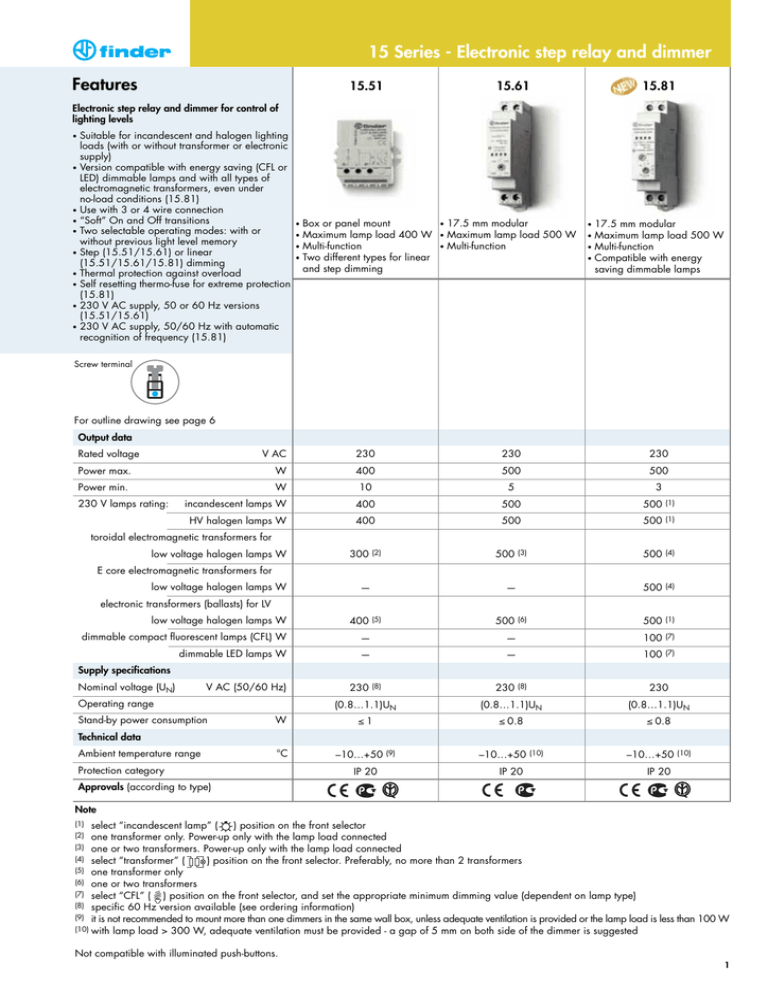
15 Series - Electronic step relay and dimmer Features 15.51 15.61 15.81 Electronic step relay and dimmer for control of lighting levels Suitable for incandescent and halogen lighting loads (with or without transformer or electronic supply) • Version compatible with energy saving (CFL or LED) dimmable lamps and with all types of electromagnetic transformers, even under no-load conditions (15.81) • Use with 3 or 4 wire connection • “Soft” On and Off transitions • Two selectable operating modes: with or without previous light level memory • Step (15.51/15.61) or linear (15.51/15.61/15.81) dimming • Thermal protection against overload • Self resetting thermo-fuse for extreme protection (15.81) • 230 V AC supply, 50 or 60 Hz versions (15.51/15.61) • 230 V AC supply, 50/60 Hz with automatic recognition of frequency (15.81) • Box or panel mount Maximum lamp load 400 W • Multi-function • Two different types for linear and step dimming 17.5 mm modular Maximum lamp load 500 W • Multi-function 17.5 mm modular Maximum lamp load 500 W • Multi-function • Compatible with energy saving dimmable lamps • • • • • • Screw terminal For outline drawing see page 6 Output data Rated voltage V AC 230 230 230 Power max. W 400 500 500 Power min. W 230 V lamps rating: 10 5 incandescent lamps W 400 500 500 3 (1) HV halogen lamps W 400 500 500 (1) 500 (4) 500 (4) 500 (1) toroidal electromagnetic transformers for low voltage halogen lamps W 300 (2) 500 (3) E core electromagnetic transformers for low voltage halogen lamps W — — electronic transformers (ballasts) for LV low voltage halogen lamps W 400 dimmable compact fluorescent lamps (CFL) W — — 100 (7) dimmable LED lamps W — — 100 (7) V AC (50/60 Hz) 230 (5) 500 (6) Supply specifications Nominal voltage (UN) Operating range Stand-by power consumption W Technical data Ambient temperature range (8) 230 Protection category 230 (0.8…1.1)UN (0.8…1.1)UN (0.8…1.1)UN ≤1 ≤ 0.8 ≤ 0.8 –10…+50 AgSnO2 °C (8) –10…+50 IP 20 (9) –10…+50 IP 20 (10) –10…+50 (10) IP 20 Approvals (according to type) Note (1) select “incandescent lamp” ( ) position on the front selector one transformer only. Power-up only with the lamp load connected (3) one or two transformers. Power-up only with the lamp load connected (4) select “transformer” ( ) position on the front selector. Preferably, no more than 2 transformers (5) one transformer only (6) one or two transformers (7) select “CFL” ( ) position on the front selector, and set the appropriate minimum dimming value (dependent on lamp type) (8) specific 60 Hz version available (see ordering information) (9) it is not recommended to mount more than one dimmers in the same wall box, unless adequate ventilation is provided or the lamp load is less than 100 W (10) with lamp load > 300 W, adequate ventilation must be provided - a gap of 5 mm on both side of the dimmer is suggested (2) Not compatible with illuminated push-buttons. 1 15 Series - Electronic step relay and dimmer Ordering information Example: type 15.51, electronic step relay and dimmer, 230 V AC. 1 5 . 5 1 . 8 . 2 3 0 . 0 4 0 Supply voltage 230 = 230 V Series Type 5 = Panel or box mount 6 = 35 mm rail (EN 60715) mount, 17.5 mm wide 8 = 35 mm rail (EN 60715) mount, 17.5 mm wide, for energy saving lamps 0 0 = Standard 4 = Only for 15.51 linear dimming Supply version 8 = AC AC input frequency 0 = 50 Hz (15.51/15.61) 50/60 Hz (15.81) 6 = 60 Hz (15.51/15.61) No. of poles 1 = 1 output Output power 4 = 400 W (15.51) 5 = 500 W (15.61/15.81) Codes 15.51.8.230.0400 15.51.8.230.0404 15.51.8.230.0460 15.61.8.230.0500 15.61.8.230.0560 15.81.8.230.0500 step dimming linear dimming step dimming, 60Hz step and linear dimming step and linear dimming, 60Hz linear dimming, 50/60Hz Technical data EMC specifications Type of test Reference standard Electrostatic discharge contact discharge EN 61000-4-2 15.51 15.61 15.81 4 kV air discharge EN 61000-4-2 Radio-frequency electromagnetic field (80 … 1,000 MHz) EN 61000-4-3 3 V/m 3 V/m 3 V/m Fast transients (burst) on supply terminals EN 61000-4-4 4 kV 2 kV 4 kV on pushbutton connection EN 61000-4-4 4 kV 2 kV 4 kV 2 kV (5-50 ns, 5 and 100 kHz) 8 kV Surges (1.2/50 µs) on supply terminals differential mode EN 61000-4-5 2 kV 2 kV Radiofrequency common mode voltage on supply terminals EN 61000-4-6 3V 3V 3V on pushbutton connection EN 61000-4-6 3V 3V 3V (0.15…80 MHz) Radiofrequency conducted emissions Radiated emissions 0.15…30 MHz EN 55014 class B 30…1,000 MHz EN 55014 class B Terminals mm2 Max. wire size AWG Screw torque Wire strip length without load with rated load Max cable length for push-button connection 2 stranded cable 1x6/2x4 1 x 10 / 2 x 10 1 x 10 / 2 x 12 Nm 0.8 mm 9 Other data Power lost to the environment solid cable 1x6/2x6 15.51 15.61 W 0.7 0.8 15.81 0.5 W 2.2 2.4 2.6 m 100 100 100 15 Series - Electronic step relay and dimmer Thermal protection and signaling LED (15.61/15.81 types) Supply voltage Thermal protection OFF — ON — ON ALARM ALARM The internal thermal protection will detect an unsafe temperature, due to overload or incorrect installation, and will turn the dimmer output off. It is possible to turn the dimmer on, by push button, only when the temperature reduces to a safe level (after 1 to 10 minutes, depending on installation conditions) and after removing the cause of the overload. Functions (15.51/15.61 types) Type 15.51...0400 Setting Step dimming Operating mode 1 (with memory): the previous light level is memorized. see Long control pulse: The light level is progressively “Operating raised or lowered through a maximum of 10 mode setup” incremental steps. Short control pulse: Alternately switches between On and Off. When switching On, the light level assumes the value set during the previous On state. 15.61 15.51...0400 see “Operating mode setup” Operating mode 2 (without memory): on switch off, the light level is not memorized. Long control pulse: The light level is progressively raised or lowered through a maximum of 10 incremental steps. 15.61 Type 15.51...0404 Short control pulse: Alternately switches On or Off between the maximum light level and the off state. Setting Linear dimming Operating mode 3 (with memory): the previous light level is memorized. see “Operating Long control pulse: The light level is progressively mode setup” raised or lowered. Short control pulse: Alternately switches between On and Off. When switching On, the light level assumes the value set during the previous On state. 15.61 15.51...0404 see “Operating mode setup” Operating mode 4 (without memory): on switch off, the light level is not memorized. Long control pulse: The light level is progressively raised or Lowered. Short control pulse: Alternately switches On or Off between the maximum light level and the off state. 15.61 Operating mode setup Type 15.51 On 15.51 operating mode 1 is preset, but it is possible to change it using the following sequence: a) remove the supply voltage; b)press the control button; c)apply the supply to the relay, keeping the button closed for 3 second; d)On button release, the light will flash twice to indicate the selection of operating mode 2, or flash once for operating mode 1. Repeating the above steps will alternately change between operating modes. Type 15.61 On 15.61 it is possible to select the required operating mode 1, 2, 3 or 4 using the front selector. 1(M) 2(M) 3(M) 4(M) = = = = Operating Operating Operating Operating mode mode mode mode 1 2 3 4 (with Memory) (without Memory) (with Memory) (without Memory) 3 15 Series - Electronic step relay and dimmer Functions (15.81 type) 15.81 Operating mode without memory: at switch-off, the light level is not memorized. Long control pulse: The light level is progressively raised or lowered in linear way. The lowest value depend on the “minimum dimming level” regulator setting. Short control pulse: Alternately switches between On and Off between the maximum light level and the off state. Operating mode with memory: the previous light level is memorized. Long control pulse: The light level is progressively raised or lowered in linear way. The lowest value dependent on the “minimum dimming level” regulator setting Short control pulse: Alternately switches between On and Off. When switching On, the light level assumes the value set during the previous On state. Type of load Selector setting With memory (M) Regulator setting Without memory (M) Incandescent lamps 230 V halogen lamps • 12/24 V halogen lamps with electronic transformer/ballast It is suggested to set the “minimum dimming level” at the lowest value, so that the complete dimming range is available. But if it is necessary to avoid too low a level of illumination, a higher value can be set. Dimmable compact fluorescent lamps (CFL) • Dimmable LED lamps It is suggested to initially set the “minimum dimming level” at an intermediate value and then if necessary, readjust for a level found to be compatible with the lamp being used. • • • • 4 12/24 V halogen lamps with toroidal or E-core electromagnetic transformer It is suggested to set the “minimum dimming level” at the lowest value, so that the complete dimming range is available. But if it is necessary to avoid too low a level of illumination, a higher value can be set. 15 Series - Electronic step relay and dimmer Wiring diagrams Note: remember to maintain a ground/earth connection for class 1 lamps. Type 15.51 - 3 wire connection Type 15.51 - 4 wire connection L L N N Type 15.61 - 3 wire connection Type 15.61 - 4 wire connection L L N N Type 15.81 - 3 wire connection Type 15.81 - 4 wire connection L L N N 5 15 Series - Electronic step relay and dimmer Outline drawings 15.51 Screw terminal 15.61 Screw terminal 15.81 Screw terminal Accessories Adaptor for panel mounting for type 15.61/15.81, plastic, 17.5 mm wide 020.01 Sheet of marker tags for type 15.61/15.81, plastic, 72 tags, 6x12 mm 060.72 Separator for panel mounting for type 15.61/15.81 020.03 020.01 060.72 020.03 6

