Switching Regulator Series
Considerations for Power Inductors
Used for Buck Converters
No.16027EAY19
A number of inductors used for buck converters are being
ferrite core, only a quarter volume is required to accumulate
sold by manufacturers and users are often at a loss as to
the same amount of energy as that of a ferrite core.
which of them to select. This application note explains the
However, since its magnetic permeability is generally lower
features and things to consider when shopping for power
than that of a ferrite core, an increasing number of windings
inductors.
are required to gain the same inductance value. Although
the metal composite type is suitable for applications requiring
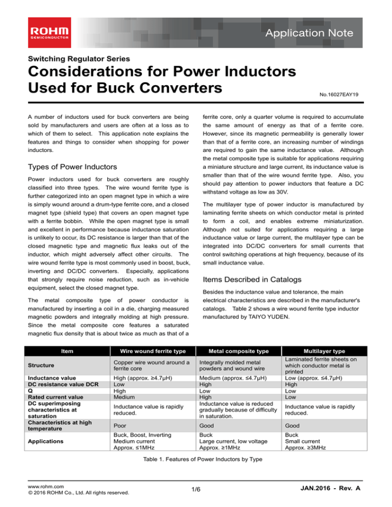
Types of Power Inductors
a miniature structure and large current, its inductance value is
smaller than that of the wire wound ferrite type. Also, you
Power inductors used for buck converters are roughly
classified into three types.
should pay attention to power inductors that feature a DC
The wire wound ferrite type is
withstand voltage as low as 30V.
further categorized into an open magnet type in which a wire
is simply wound around a drum-type ferrite core, and a closed
The multilayer type of power inductor is manufactured by
magnet type (shield type) that covers an open magnet type
laminating ferrite sheets on which conductor metal is printed
with a ferrite bobbin. While the open magnet type is small
to form a coil, and enables extreme miniaturization.
and excellent in performance because inductance saturation
Although not suited for applications requiring a large
is unlikely to occur, its DC resistance is larger than that of the
inductance value or large current, the multilayer type can be
closed magnetic type and magnetic flux leaks out of the
integrated into DC/DC converters for small currents that
inductor, which might adversely affect other circuits.
control switching operations at high frequency, because of its
The
small inductance value.
wire wound ferrite type is most commonly used in boost, buck,
inverting and DC/DC converters.
Especially, applications
Items Described in Catalogs
that strongly require noise reduction, such as in-vehicle
equipment, select the closed magnet type.
The
metal
composite
type
of
Besides the inductance value and tolerance, the main
power
conductor
is
electrical characteristics are described in the manufacturer's
manufactured by inserting a coil in a die, charging measured
catalogs. Table 2 shows a wire wound ferrite type inductor
magnetic powders and integrally molding at high pressure.
manufactured by TAIYO YUDEN.
Since the metal composite core features a saturated
magnetic flux density that is about twice as much as that of a
Item
Structure
Inductance value
DC resistance value DCR
Q
Rated current value
DC superimposing
characteristics at
saturation
Characteristics at high
temperature
Applications
Wire wound ferrite type
Metal composite type
Copper wire wound around a
ferrite core
Integrally molded metal
powders and wound wire
High (approx. ≥4.7μH)
Low
High
Medium
Medium (approx. ≤4.7μH)
High
Low
High
Inductance value is reduced
gradually because of difficulty
in saturation.
Inductance value is rapidly
reduced.
Multilayer type
Laminated ferrite sheets on
which conductor metal is
printed
Low (approx. ≤4.7μH)
High
Low
Low
Inductance value is rapidly
reduced.
Poor
Good
Good
Buck, Boost, Inverting
Medium current
Approx. ≤1MHz
Buck
Large current, low voltage
Approx. ≥1MHz
Buck
Small current
Approx. ≥3MHz
Table 1. Features of Power Inductors by Type
www.rohm.com
© 2016 ROHM Co., Ltd. All rights reserved.
1/6
JAN.2016 - Rev. A
Application Note
Considerations for Power Inductors Used for Buck Converters
(Source: TAIYO YUDEN Inductor Catalog in 2016)
Table 2. TAIYO YUDEN Catalog
metal composite type is higher than that of the wire wound
DC Resistance
ferrite type, the inductance value gradually decreases as
shown in Figure 3 regardless of the increase in current.
DC resistance is a resistance of a wound wire (copper wire),
and affects efficiency at high current.
Since heat is
The DC superimposed allowable current value is judged as to
generated in the inductor via resistance in proportion to the
whether or not the specification satisfies the inductor current
square of inductor current, a higher resistance value
peak current value shown in Figure 1. You should select an
increases the energy loss caused by heat generation and
accordingly lowers the conversion efficiency.
inductor
Since an
having
a
sufficient
leeway
in
the
inductor
specification.
inductor having a low series resistance is subject to up-sizing
and increase in cost, low resistance and high efficiency are in
Temperature Rise Allowable Current
a trade-off relationship. Compared to the wire wound ferrite
type of power inductor, the metal composite type requires an
Temperature rise allowable current is a current value that
increasing number of windings (of copper wire) to gain the
represents how the inductor generates heat against current
same inductance value, which shows a tendency toward
flowing to the inductor.
large DC resistance.
characteristics. The example in Table 2 lists the DC values
Figure 4 shows an example of
when the inductor temperature rises by 40°C. This condition
varies depending on the manufacturer and inductor series, as
DC Superimposed Allowable Current
well as the difference in heat radiation characteristics of the
DC superimposed allowable current represents how the
measurement board and the difference in measurement
inductance value changes against the current flowing in the
position. Therefore, due consideration must be taken when
inductor. Table 2 shows a list of DC current values when the
comparing with other inductors.
inductance value reduces by 30% from the initial value. This
condition varies depending on the manufacturer and inductor
The temperature rise allowable current value is judged as to
series. Therefore, due consideration must be taken when
whether or not the specification satisfies the inductor current
comparing with other inductors.
average value shown in Figure 1.
You should select an
inductor having a sufficient leeway in the maximum value of
Figure 2 shows an example of characteristics. When DC
the inductor specification.
current flows in the inductor, magnetic saturation starts in the
ferrite in response to the increase in current, and the
inductance value lowers due to deterioration of magnetic
permeability.
Since the saturated magnetic density of the
∆
IL
Ripple current
Peak current
Average current
∆
2
t
Figure 1. Inductor Current
www.rohm.com
© 2016 ROHM Co., Ltd. All rights reserved.
2/6
JAN.2016 - Rev. A
Application Note
Considerations for Power Inductors Used for Buck Converters
10
10
0
0
-10
-10
Inductance change (%)
Inductance change (%)
-30%
-20
-30
-40
-50
-60
Metal composite
-30%
-20
-30
Multilayer
-40
-50
-60
NRH2410TR68NN4 (TAIYO YUDEN)
-70
Ferrite
-70
-80
-80
0
1
2 2.25
DC Current (A)
3
0
1
2
3
4
DC Current (A)
Figure 2. Example of DC Superimposed Characteristics in Table 2
(Source: TAIYO YUDEN Engineering Data in 2015)
Figure 3. DC Superimposed Characteristics by Structure
Wire wound ferrite type: NRH2410T1R0 (TAIYO YUDEN)
Metal composite type: MAKK2520T1R0 (TAIYO YUDEN)
Multilayer type: CKP25201R0-T (TAIYO YUDEN)
(Source: TAIYO YUDEN Engineering Data in 2015)
60
NRH2410T1R0 (TAIYO YUDEN)
Temperature Rise : ΔT (℃)
50
40
30
20
10
0
0
0.5
1
1.5 1.7
2
DC Current (A)
Figure 4. Example of Temperature Rise Characteristics in Table 2
(Source: TAIYO YUDEN Engineering Data in 2015)
5
10
Metal composite
-20℃ - +125℃
8
Inductance Change : ΔL (%)
Inductance (µH)
4
Ferrite
+125℃
+85℃
+65℃
+20℃
0℃
-20℃
3
2
1
Ferrite
6
4
2
0
-2
-4
Metal composite
-6
-8
-10
0
0
1
2
3
4
-50
5
0
25
50
75
100
Figure 6. Temperature Characteristics
Figure 5. Temperature Characteristics
Wire wound ferrite type: NRS5014T4R7 (TAIYO YUDEN)
Metal composite type: MDPK5050T4R7 (TAIYO YUDEN)
(Source: TAIYO YUDEN Engineering Data in 2015)
www.rohm.com
© 2016 ROHM Co., Ltd. All rights reserved.
-25
Ambient Temperature (℃)
DC Current (A)
3/6
Wire wound ferrite type: NRS5014T4R7 (TAIYO YUDEN)
Metal composite type: MDPK5050T4R7 (TAIYO YUDEN)
(Source: TAIYO YUDEN Engineering Data in 2015)
JAN.2016 - Rev. A
Application Note
Considerations for Power Inductors Used for Buck Converters
as it will influence the efficiency in the entire current region.
Temperature Characteristics
Since this data is hardly opened to the public, you have to
obtain it from inductor suppliers.
As the inductance value of the buck converter circuit changes,
Figures 5 and 6 show the
Figure 8 shows a power inductor equivalent circuit model.
temperature characteristics of the wire wound ferrite type and
The AC resistance data (Figure 9) is provided in the form of a
the metal composite type of power inductors.
composite value of
so does the ripple value.
wound
ferrite
type
characteristics
of
features
magnetic
significant
materials
and,
The wire
temperature
. When the frequency is low,
is dominant because the value of
therefore,
frequency increases,
deterioration of DC superimposed characteristics especially
at high temperature.
and is small.
As
also increases.
As shown in Figure 10, loss against AC is generated by
The metal composite type incurs
copper loss of the wound wire (skin effect, proximity effect)
minimal change in inductance value due to temperature
and iron loss of the magnetic materials (hysteresis loss, eddy
changes because it uses magnetic metal materials that are
current loss and net loss).
excellent in both magnetic saturation and temperature
characteristics. The wire wound ferrite type is subject to a
Wire wound resistance is a loss due to DC.
vicious spiral where the current peak value increases,
component of wound wire (copper) adversely affects loss and
temperature further rises and, accordingly, the inductance
takes up most of inductor loss at a large current.
value further decreases, through the decrease in inductance
The resistance
Skin effect is a phenomenon in which current density
value is caused by temperature rise from self-heating.
becomes high on the surface of the conductor and becomes
low in its center when high frequency current flows through
Occurrence of Problems Due to Decrease in
Inductance Value
the conductor.
As frequency becomes high, current
concentrates on the surface more. (Example: Copper wire:
As mentioned above, when DC flows into the inductor, the
100 kHz and surface skin depth: 0.21mm, copper wire: 1MHz
inductance value decreases due to magnetic saturation.
and surface skin depth: 0.066mm, and copper wire: 10MHz
However, if the operating allowable current has no leeway
and surface skin depth: 0.021mm).
against the peak current value actually flowing, a rapid
Proximity effect is a phenomenon in which the repulsive force
increase in current may destabilize control.
created by AC flowing through adjacent conductors in the
If the inductor allowable current has sufficient leeway against
same direction or the suction force created by AC flowing
the peak current, the degree of decrease in inductance value
through adjacent conductors in the reverse direction deviates
is small, which will enable control as designed.
current in the conductors.
If no leeway is provided, the inductance value decreases due
to magnetic saturation in response to the increase in current,
and peak current further increases due to the decrease in the
Current increases in
IL
inductance value as shown in Figure 7. This phenomenon
response to the rapid
may activate the overcurrent protection circuit and stop output.
decrease in inductor
If current increases too rapidly, the overcurrent protection
value.
operation may not keep up with this rapid increase, resulting
Increase in current
in IC damage.
as designed
To prevent a rapid decrease in the inductance value in
response to the increase in peak current, it is necessary to
select inductance in consideration of the inductor allowable
t
current characteristics.
Figure 7. Increase in Current in Response to Decrease in
Inductance Value
Power Inductor Loss
Serial resistance
is given in catalogs as an inductor loss
that will influence the efficiency in the large current region.
When switching frequency becomes as high as several MHz,
resistance
against AC will also be an important element,
www.rohm.com
© 2016 ROHM Co., Ltd. All rights reserved.
4/6
JAN.2016 - Rev. A
Application Note
Considerations for Power Inductors Used for Buck Converters
Hysteresis loss is generated when the core changes the
in details.
magnetic field direction. It is represented by a hysteresis
selection tools, you may use them as reference when
loop and its volume is proportional to the area surrounded by
selecting products.
the loop. For AC, the potential energy loss is proportional to
the number of turns in the loop.
Since these figures are provided merely as
Calculate the inductance value by referring to the calculation
The resultant loss is
method, and make sure that the calculated value is specified
proportional to the frequency.
in the IC data sheet.
.
Find the one in manufacturer catalogs that meets the required
:Hysteresisloss
electrical characteristics and dimensions.
:Frequency
:Maximummagneticfluxdensity
Rac
:Constantofproportionality
Rdc
By flowing AC in a coil wound around a conductive core, eddy
current corresponding to change in magnetic flux flows. This
Cp
current generates heat due to the electric resistance of the
core material.
L
The resultant loss is proportional to the
square of the frequency.
Figure 8. Power Inductor Equivalent Circuit Model
100000
NS10165 T4R7NNA (TAIYO YUDEN)
: Eddycurrentloss
10000
AC Resistance : Rs (Ω)
:Ironplatethickness
:Frequency
:Maximummagneticfluxdensity
: Resistivityofmagneticsubstance
: Constantofproportionality
Net loss is a loss other than hysteresis loss and eddy current
loss.
1000
100
10
1
0.1
Inductor manufacturers promote development of
products that reduce copper loss and iron loss.
0.01
0.1
Inductor Selection Procedures
Select several types of inductors.
1
10
Frequency (MHz)
100
Figure 9. AC Resistance Frequency Characteristics
Table 1 shows the
(Source: TAIYO YUDEN Engineering Data in 2015)
features of inductors and Figure 11 shows the numeric values
Wound wire resistance
Copper loss
Loss against DC
Skin effect
Proximity effect
Total loss
Hysteresis loss
Iron loss
Loss against AC
Eddy current loss
Net loss
Figure 10. Inductor Loss
www.rohm.com
© 2016 ROHM Co., Ltd. All rights reserved.
5/6
JAN.2016 - Rev. A
Application Note
Considerations for Power Inductors Used for Buck Converters
Inducta nce
0.47μH
Ferrite Wo und
1μH
4.7μH
Better
Switchi ng freq uency
10μH
100μH
100kHz
Metal Composite
Multilayer
Multilayer
Output cur rent
1A
3MHz
Ferrite Wo und
Best
Metal Composite
100mA
1MHz
Power rail voltage
10A
5V
Ferrite Wo und
Ferrite Wo und
Metal Composite
Metal Composite
Multilayer
Multilayer
12V
24V
48V
Figure 11. Conceptual View of Inductor Type Selection Process
www.rohm.com
© 2016 ROHM Co., Ltd. All rights reserved.
6/6
JAN.2016 - Rev. A
Notice
Notes
1) The information contained herein is subject to change without notice.
2) Before you use our Products, please contact our sales representative and verify the latest specifications :
3) Although ROHM is continuously working to improve product reliability and quality, semiconductors can break down and malfunction due to various factors.
Therefore, in order to prevent personal injury or fire arising from failure, please take safety
measures such as complying with the derating characteristics, implementing redundant and
fire prevention designs, and utilizing backups and fail-safe procedures. ROHM shall have no
responsibility for any damages arising out of the use of our Poducts beyond the rating specified by
ROHM.
4) Examples of application circuits, circuit constants and any other information contained herein are
provided only to illustrate the standard usage and operations of the Products. The peripheral
conditions must be taken into account when designing circuits for mass production.
5) The technical information specified herein is intended only to show the typical functions of and
examples of application circuits for the Products. ROHM does not grant you, explicitly or implicitly,
any license to use or exercise intellectual property or other rights held by ROHM or any other
parties. ROHM shall have no responsibility whatsoever for any dispute arising out of the use of
such technical information.
6) The Products are intended for use in general electronic equipment (i.e. AV/OA devices, communication, consumer systems, gaming/entertainment sets) as well as the applications indicated in
this document.
7) The Products specified in this document are not designed to be radiation tolerant.
8) For use of our Products in applications requiring a high degree of reliability (as exemplified
below), please contact and consult with a ROHM representative : transportation equipment (i.e.
cars, ships, trains), primary communication equipment, traffic lights, fire/crime prevention, safety
equipment, medical systems, servers, solar cells, and power transmission systems.
9) Do not use our Products in applications requiring extremely high reliability, such as aerospace
equipment, nuclear power control systems, and submarine repeaters.
10) ROHM shall have no responsibility for any damages or injury arising from non-compliance with
the recommended usage conditions and specifications contained herein.
11) ROHM has used reasonable care to ensur the accuracy of the information contained in this
document. However, ROHM does not warrants that such information is error-free, and ROHM
shall have no responsibility for any damages arising from any inaccuracy or misprint of such
information.
12) Please use the Products in accordance with any applicable environmental laws and regulations,
such as the RoHS Directive. For more details, including RoHS compatibility, please contact a
ROHM sales office. ROHM shall have no responsibility for any damages or losses resulting
non-compliance with any applicable laws or regulations.
13) When providing our Products and technologies contained in this document to other countries,
you must abide by the procedures and provisions stipulated in all applicable export laws and
regulations, including without limitation the US Export Administration Regulations and the Foreign
Exchange and Foreign Trade Act.
14) This document, in part or in whole, may not be reprinted or reproduced without prior consent of
ROHM.
Thank you for your accessing to ROHM product informations.
More detail product informations and catalogs are available, please contact us.
ROHM Customer Support System
http://www.rohm.com/contact/
www.rohm.com
© 2016 ROHM Co., Ltd. All rights reserved.
R1102A


