INDOOR AIR QUALITY
VENTILATION
ENERGY RECOVERY
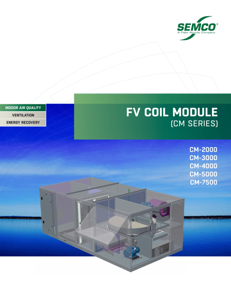
FV COIL MODULE
(CM SERIES)
CM-2000
CM-3000
CM-4000
CM-5000
CM-7500
Economical compliance
with the ASHRAE
Standard 62.
Improves the indoor air
quality of existing facilities
by increasing the outdoor
air quantity compared to
traditional systems.
The SEMCO CM (Coil Module) has been specifically designed to
complement and attach directly to the FV series outdoor air
Reliable operation with
minimal maintenance.
pre-conditioner.
This powerful combination provides an effective solution to
ASHRAE Standard 62, providing an increase in the outdoor
ENVIRONMENT
ECONOMICAL
EXPERTISE
air quantity (5 to 20 cfm/person) without significantly
INTELLIGENT
increasing
operating costs.
INNOVATIVE
INVESTMENT
The CM Series offers several heating and cooling options.
The cooling options include either chilled water or DX
cooling coils. The heating options include hot water, electric
ENVIRONMENT
ECONOMICAL
EXPERTISE
2
coil, or INTELLIGENT
hot gas reheat.
INNOVATIVE
INVESTMENT
FV COIL MODULE SERIES
OUTDOOR AIR.
QUANTITY AND QUALITY.
•
Simple integration with single source responsibility.
•
Provides performance beyond that of a standard
rooftop unit.
•
Low profile design offers an aesthetically pleasing
solution.
•
Indoor and outdoor installation configurations.
•
Horizontal & down flow configurations.
•
Multiple heating and cooling options.
•
Numerous coil materials available.
•
Galvanized steel cabinet, with optional enamel finish.
•
Unit is constructed to ensure a watertight design.
•
Unit is insulated to minimize energy loss.
•
Filters are ASHRAE compliant.
•
Easy access to all components through access doors.
•
Internal piping for rooftop installations.
Coil Dimensions & Internal Pressure Losses
Model#
Coil Size Dimensions
Fin L (in.)
Fin H (in.)
CM-2000
26.0
21.0
CM-3000
30.0
33.0
CM-4000
36.0
36.0
CM-5000
44.0
39.0
CM-7500
54.0
48.0
Airflow
(scfm)
Chilled Water*
6 Row (in. w.g.) 8 Row (in. w.g.)
Hot Water*
1 Row (in. w.g.)
2” Filter
(in. w.g.)
1000
.14
.19
.03
.01
2000
.48
.64
.11
.11
1500
.10
.14
.02
.01
3000
.35
.46
.08
.12
2000
.11
.14
.02
.02
4000
.36
.48
.08
.17
2500
.10
.13
.02
.06
5000
.32
.43
.07
.24
3750
.10
.13
.02
.01
7500
.32
.43
.08
.15
* Note: pressure losses based on coils with ‘B’ fin / 8 FPI configuration.
3
UNIT & CURB
DIMENSIONS
Curb Dimensions & Detail
D
CM Module
Z
A
E
DD
GG
Nailer
3.25"
FF
F
SERVICE CLEARANCE
X
EA
SECTION H-H
G
STD.
RA
H
Roof Curb
Elevation View
FV UNIT
B
H
H
CM Unit
FV Unit
BB
COIL
SPACE
J
DD
EE
STD.
SA
I
AA
Electric Heater
Panel
Y
CC
Plan View
K
M
OA
SERVICE CLEARANCE
L
N
O
P
OPT.
RA
C
OPT.
SA
T
S
Q
4
R
Fan
Access
Door
Electric
Heater
Panel
Filter
Access
Door
FV UNIT
SERVICE
CLEARANCE
FV COIL MODULE SERIES
The CM Series is available in five cabinet sizes ranging in airflow capacity from 800 scfm to 9,000 scfm. Each module
can be configured for indoor or outdoor installations, and horizontal or vertical airflow.
Dimensions (inches)
Model#
Net Wt.
(lbs.)
A
B
C
D
E
F
G
H
I
J
K
L
M
CM-2000
550*
72.0
51.5
32.4
109.0
4.5
18.0
4.5
10.0
12.0
11.4
3.5
10.4
2.7
CM-3000
900*
84.0
64.8
47.7
129.0
10.0
17.0
7.0
17.0
13.1
12.6
4.9
11.4
7.0
CM-4000
1300*
92.0
78.8
51.5
146.0
7.9
20.0
5.3
19.0
14.6
16.4
4.0
13.4
5.3
CM-5000
1300*
92.0
78.8
51.5
146.0
7.9
20.0
5.3
19.0
18.6
16.4
4.0
15.9
5.3
CM-7500
1850*
92.0
95.3
58.6
156.6
7.9
27.3
5.1
23.0
18.6
22.3
4.0
15.9
3.3
Model#
Dimensions (inches)
N
O
P
Q
R
S
T
X
Y
Z
AA
BB
CC
DD
EE
FF
GG
CM-2000
12.6
10.0
14.2
11.8
11.5
5.0
10.3
24.0
44.0
37.0
47.4
70.0
104.9
4.1
1.7
14.0
2.0
CM-3000
17.0
6.8
17.0
13.1
12.6
9.6
11.4
24.0
44.0
45.0
60.6
82.3
124.8
4.1
1.7
14.0
3.0
CM-4000
19.0
17.2
20.0
14.6
16.4
10.2
13.4
24.0
44.0
54.0
74.6
89.9
141.8
4.1
1.7
14.0
3.0
CM-5000
19.0
17.2
20.0
18.6
16.4
12.2
15.9
24.0
44.0
54.0
74.6
89.9
141.8
4.1
1.7
14.0
3.0
CM-7500
25.0
17.7
25.0
18.6
22.3
12.2
15.9
24.0
54.0
64.6
91.1
89.9
152.4
4.1
1.7
14.0
3.0
* - Weight includes maximum size coils with fluid. Does not include weight of the FV unit. Standard piping connections shown.
5
DESIGN
SPECIFICATIONS
Casing
Standard panels shall be 20 gauge galvanized steel, lined with 1/2 inch thick neoprene insulation where required. The
housing shall be supported by a formed structural base that forms a pan to ensure weather tight construction. Lifting
holes shall be provided at the unit base. All access doors shall be hinged. Units shall have a weatherproof sheet metal
roof. The exterior of the unit shall be coated with an epoxy primer and a polyurethane enamel painting system for
added protection. Painting system shall be rated to meet a 750-hour salt spray test.
Fan
Fan shall be double width double inlet design with forward curve type wheels. The blades shall be designed for
maximum efficiency and quiet operation. Impellers shall be statically and dynamically balanced.
Fan shall be driven by a motor using belt and sheaves. Motor shall be standard NEMA frame with open drip-proof
enclosure. V-belt drive shall be designed for a minimum 1.2 service factor.
Chilled Water, DX and Hot Water Coils
Primary surface shall be round seamless .020-inch thick copper tube on 1.5-inch centers, staggered in the direction of
airflow. All joints shall be brazed.
Secondary surface shall consist of .006 inch rippled aluminum plate fins for higher capacity and structural strength. Fins
shall have full drawn collars to provide a continuous surface cover over the entire tube for maximum heat transfer. Bare
copper tube shall not be visible between fins and the fins shall have no openings punched in them to accumulate lint
and dirt. Tubes shall be mechanically expanded into the fins to provide a continuous primary to secondary compression
bond over the entire finned length for maximum heat transfer rates.
Casings shall be constructed of continuous galvanized steel. Coil side plates shall be of reinforced flange type.
Coils shall have equal pressure drop through all circuits. Coils shall be circuited for counter flow heat transfer to
provide the maximum heat transfer rates.
Headers on coils shall be seamless copper tubing. The headers shall have intruded tube holes to provide a large
brazing surface for maximum strength and inherent flexibility. Supply and return connections on water coils shall be
steel with male pipe threads. DX coils shall have copper sweat connections.
6
FV COIL MODULE SERIES
The complete coil core shall be tested with 315 psig air pressure under warm water and be suitable for operation at
250 psig working pressures.
Individual tube tests and core tests before installation of headers shall not be considered satisfactory. Water cooling
coils shall be circuited for drain ability. Use of internal restrictive devices to obtain turbulent flow shall not be acceptable.
Vents and drains shall be furnished on all water coils. Coils shall be rated in accordance with ARI.
Coils shall be mounted in galvanized holding racks. Water coil drain and vent connections are accessible from the
interior of the unit. Cooling coils shall be mounted in an insulated pitched 304 stainless steel condensate pan.
Electric Heating Coil
Where scheduled, electric coil shall be either the open element or enclosed element electric resistance type. Heater
shall include main disconnect switch, fusing as required, magnetic contactors, control circuit transformer, pressure
type air flow interlock switch and manual and auto reset thermal cutout over current protection. The electric coil shall
require a separate power feeder connection in addition to the power connection to the main unit electrical panel.
7
www.semcohvac.com
SEMCO FV COIL MODULE SERIES BR - DWP
WE BRING
AIR TO LIFE
WWW.SEMCOHVAC.COM | FV+CM SERIES | 20160309
SEMCO® is a global leader in air
management. We specialize in the
design and manufacture of a wide
range of air climate and air movement
solutions. Our collective experience
is unrivaled.
WE BRING AIR TO LIFE
Our constant aim is to provide systems that
precisely deliver the best indoor air quality
and performance, as well as maximize
energy efficiency.
SEMCO® A Fläkt Woods Company
Corporate Headquarters
1800 East Pointe Drive
Columbia, Missouri 65201 USA
573 443 1481
sales.semco@flaktwoods.com
To learn more about SEMCO offerings and to contact your nearest representative please visit
www.semcohvac.com
SEMCO embraces a policy of continuous development and improvement, the right is reserved to supply products which may differ from those illustrated and described in this
publication. Certified dimensions will be supplied upon request on receipt of order.
© SEMCO LLC 2016 All Rights Reserved. EXCLU-SIEVE and the SEMCO logo are registered Trademarks of SEMCO LLC.


