Application Bulletin AB-25
IsoLoop® Isolators Enable Next-Generation Switching-Mode Power Supplies
New 2.5 kV MSOP isolators allow denser, more precise, and more reliable power supplies
Switching-Mode Power Supplies (SMPS) are widely used because of their power density, efficiency, and reliability.
SMPS technology has steadily improved over the years. This Application Bulletin reviews major milestones in the
®
evolution of SMPS technology, and examines the benefits of new 2.5 kV MSOP IsoLoop Isolators to enable betterthan-ever power supplies.
SMPS Evolution
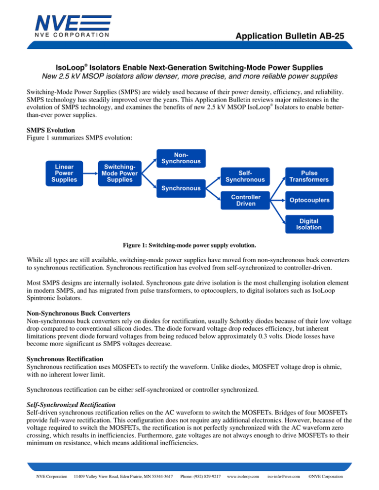
Figure 1 summarizes SMPS evolution:
Linear
Power
Supplies
SwitchingMode Power
Supplies
NonSynchronous
SelfSynchronous
Pulse
Transformers
Controller
Driven
Optocouplers
Synchronous
Digital
Isolation
Figure 1: Switching-mode power supply evolution.
While all types are still available, switching-mode power supplies have moved from non-synchronous buck converters
to synchronous rectification. Synchronous rectification has evolved from self-synchronized to controller-driven.
Most SMPS designs are internally isolated. Synchronous gate drive isolation is the most challenging isolation element
in modern SMPS, and has migrated from pulse transformers, to optocouplers, to digital isolators such as IsoLoop
Spintronic Isolators.
Non-Synchronous Buck Converters
Non-synchronous buck converters rely on diodes for rectification, usually Schottky diodes because of their low voltage
drop compared to conventional silicon diodes. The diode forward voltage drop reduces efficiency, but inherent
limitations prevent diode forward voltages from being reduced below approximately 0.3 volts. Diode losses have
become more significant as SMPS voltages decrease.
Synchronous Rectification
Synchronous rectification uses MOSFETs to rectify the waveform. Unlike diodes, MOSFET voltage drop is ohmic,
with no inherent lower limit.
Synchronous rectification can be either self-synchronized or controller synchronized.
Self-Synchronized Rectification
Self-driven synchronous rectification relies on the AC waveform to switch the MOSFETs. Bridges of four MOSFETs
provide full-wave rectification. This configuration does not require any additional electronics. However, because of the
voltage required to switch the MOSFETs, the rectification is not perfectly synchronized with the AC waveform zero
crossing, which results in inefficiencies. Furthermore, gate voltages are not always enough to drive MOSFETs to their
minimum on resistance, which means additional inefficiencies.
NVE Corporation
11409 Valley View Road, Eden Prairie, MN 55344-3617
Phone: (952) 829-9217
www.isoloop.com
iso-info@nve.com
©NVE Corporation
Application Bulletin AB-25
Controller-Driven Synchronous Rectification
Controller-driven synchronous rectification uses signals from the pulse-width modulation controller to drive the
rectification MOSFETs. This maximizes efficiency by allowing nearly perfect synchronization with the AC waveform.
It also requires just two MOSFETs rather than four.
Demanding applications use controller-driven rectification because it provides maximum efficiency, minimum size,
and minimum heating. However, controller-driven rectification provides an additional challenge of high-speed
isolation of the MOSFET gate drivers from the controller.
Electrical Isolation
In most applications, power supply outputs must be electrically isolated from inputs for safety and to prevent noise and
ground loops. SMPS can use either external isolation transformers or internal isolation. External isolation is becoming
less common because it requires a large transformer.
The key agency requirement for 220/240 volt SMPS internal isolation elements is 2.5 kVRMS for one minute. This
required isolation voltage is more than an order of magnitude higher than mains voltage to ensure more than ample
margin for surges and transients.
The typical SMPS circuit in Figure 2 shows the three signals that must typically cross the SMPS isolation barrier: a
transformer isolates the pulse-width modulation controller from the output voltage; the output error amplifier providing
isolated feedback; and two isolation channels to drive the synchronous gate driver.
VIN
Isolation
Barrier
LM5035C
PWM Controller
VOUT
LM5110
Gate
Driver
IL711V-1E
Isolator
Linear
opto-coupler
Error
Amplifier
Voltage
Reference
Figure 2: Typical SMPS circuit.
2
NVE Corporation
11409 Valley View Road, Eden Prairie, MN 55344-3617
Phone: (952) 829-9217
www.isoloop.com
iso-info@nve.com
©NVE Corporation
Application Bulletin AB-25
Isolated Elements
Each of the three isolation elements has different requirements.
The transformer is inherently isolated, and its macroscopic dimensions make high isolation voltages straightforward.
The isolated analog error feedback system needs to be precise because it limits the output precision, but it does not
need high linearity or accuracy because it is part of a closed-loop system. This element does not require high speed
because the error is DC, and feedback only needs to be fast enough to accommodate line and load changes, component
drift, and environmental changes.
Isolating the controller from the MOSFET gate driver is perhaps the most challenging isolation element in modern
SMPS. Precise synchronization with the AC waveform is critical to efficiency, so these isolators must be much faster
than the switching frequency. Minimizing pulse-width distortion minimized dead time and allows energy transfer for
more of the switching period. Delays or distortion from the isolator also cause the FETs to switch after the AC
waveform zero crossing. This results in transients that can cause spurious switching. Ironically, the isolators
themselves can be vulnerable to these common mode transients. Therefore, in addition to speed and distortion,
transient immunity is an important figure of merit for gate-driver isolators.
Gate-Driver Isolators
Common gate-driver isolator options are pulse transformers, optocouplers, and digital isolators.
Pulse Transformers
Gate drive transformers were used for gate drive isolation in the early days of synchronous SMPS. Advantages are that
transformers can sometimes transfer enough power to drive the MOSFET directly, the transformers are generally
rugged, have high isolation voltage, and good long-term reliability. Unfortunately they are larger than optocouplers or
solid-state isolators. Also, because they are inductive, they can only transmit limited pulse widths that constrain control
range.
Optocouplers
Optocouplers do not have the pulse-width limitations of gate drive transformers and tend to be smaller. They also have
the advantage of being “quiet” for EMI. On the other hand, optocouplers are relatively slow, causing drive waveform
distortion and imprecise rectification. They also have relatively low transient immunity, making them susceptible to
spurious switching. Finally, optical couplers tend to drift and eventually fail as their LEDs degrade over time. Limited
operating life is particularly problematic. Despite their limitations, optocouplers remain popular for isolating analog
error feedback because next-generation digital isolators are not well-suited for analog signals.
Digital Isolators
Non-optical digital isolators are replacing optocouplers and pulse transformers in many applications, including gate
drive isolation. They are generally faster than optocouplers, have higher transient immunity, and longer operating life.
Three digital isolator types are used for gate isolation: inductive, capacitive, and spintronic.
Inductive isolators use radio-frequency carriers to transmit data through miniature antennas or transformers. Many of
these devices are faster than optocouplers, but the carrier frequencies limit pulse position accuracy. They are also
generally smaller than optocouplers and have higher transient immunity, and longer operating life. Operating life is
limited by the isolation barrier in these devices. Barriers are very thin (less than one one-thousandth of an inch)
polymers or oxides. The barriers must withstand high voltages, and the small dimensions make them susceptible to
diffusion or partial-discharge failures. Operating lives of inductive digital isolators are 50 to 100 years, which is longer
than optocouplers, but there is a statistical chance of any particular device failing much sooner.
3
NVE Corporation
11409 Valley View Road, Eden Prairie, MN 55344-3617
Phone: (952) 829-9217
www.isoloop.com
iso-info@nve.com
©NVE Corporation
Application Bulletin AB-25
Capacitive isolators use a changing electric field to transmit data across the isolation barrier. Like inductive isolators,
this requires high-frequency signaling, leading to imprecision and EMI. With life specifications of 13 years, available
capacitive isolators are less reliable than other digital isolators.
As shown in the Figure 3,NVE’s IsoLoop Spintronic Isolators transmit data using magnetics rather than light, with
advantages of speed and precision. Because they do not have RF carriers or refresh clocks, spintronic isolators radiate
very little EMI. This is important for meeting standards such as EN55022-B or FCC Part B. Like other digital isolators,
IsoLoop Isolators use thin barriers, overcome reliability issues with a unique ceramic / polymer composite barrier.
IsoLoop Isolator life is specified as 44000 years, so these parts do not significantly contribute to overall SMPS failure
rates.
Signal Transmitted
by Magnetic Field
Light Coupling
CurrentMode
Input
Isolated
Output
LED
Clear Isolation
Dielectric
Isolated
Output
Digital
Input
Phototransistor
Thin-Film Galvanic
Isolation Dielectric
GMR Resistors
Figures 3a and 3b: Optocoupler (left) compared to IsoLoop Isolator (right).
Optocouplers use light to transmit data; IsoLoop Isolators uses magnetics and electron spin.
Future Trends
SMPS are expected to continue to become smaller more efficient, and more reliable.
Smaller
Manufacturers are shrinking SMPS components. The PWM controller and gate driver in Figure 2, for example, are
both available in small, leadless packages (the LM5035 in a WQFN-24 and the LM5110 in a WSON-10). IL711V-1E,
MSOP-8, 2.5 kV isolators, introduced in late 2014, are half the footprint area of SOIC-8 isolators, which were
previously the smallest 2.5 kV isolators available. Faster electronics and higher operating frequencies will allow
smaller inductive components.
More Efficient
MOSFET manufacturers are constantly reducing drain-source resistance to minimize losses, and reducing total gate
charge for speed. Gate drivers are also becoming faster and therefore more efficient.
More Reliable
Error amplifier isolation is becoming the weak link in SMPS reliability. Hybridized digital isolation amplifiers (i.e.,
analog-to-digital modulators and demodulators separated by isolators), may become precise and inexpensive enough to
replace the widely-used analog optocouplers. NVE is also developing analog spintronic couplers.
Conclusion
®
IsoLoop Isolators are ideal for gate driver isolation. Key features for this application include:
• 2500 VRMS isolation in MSOP-8 for smallest footprint (IL711V-1E)
• 1000 VRMS Working Voltage in wide-body SOIC-16 for best working voltage (IL711VE)
• 300 ps pulse width distortion and 100 ps pulse jitter for best signal fidelity
• Best-in-class 50 kV/µs transient immunity
• Best-in-class EMI emissions
• 44000 year barrier life for system reliability
4
NVE Corporation
11409 Valley View Road, Eden Prairie, MN 55344-3617
Phone: (952) 829-9217
www.isoloop.com
iso-info@nve.com
©NVE Corporation
Application Bulletin AB-25
Limited Warranty and Liability
Information in this document is believed to be accurate and reliable. However, NVE does not give any representations or warranties, expressed or
implied, as to the accuracy or completeness of such information and shall have no liability for the consequences of use of such information.
In no event shall NVE be liable for any indirect, incidental, punitive, special or consequential damages (including, without limitation, lost profits,
lost savings, business interruption, costs related to the removal or replacement of any products or rework charges) whether or not such damages
are based on tort (including negligence), warranty, breach of contract or any other legal theory.
Right to Make Changes
NVE reserves the right to make changes to information published in this document including, without limitation, specifications and product
descriptions at any time and without notice. This document supersedes and replaces all information supplied prior to its publication.
Use in Life-Critical or Safety-Critical Applications
Unless NVE and a customer explicitly agree otherwise in writing, NVE products are not designed, authorized or warranted to be suitable for use
in life support, life-critical or safety-critical devices or equipment. NVE accepts no liability for inclusion or use of NVE products in such
applications and such inclusion or use is at the customer’s own risk. Should the customer use NVE products for such application whether
authorized by NVE or not, the customer shall indemnify and hold NVE harmless against all claims and damages.
Applications
Applications described in this datasheet are illustrative only. NVE makes no representation or warranty that such applications will be suitable for
the specified use without further testing or modification.
Customers are responsible for the design and operation of their applications and products using NVE products, and NVE accepts no liability for
any assistance with applications or customer product design. It is customer’s sole responsibility to determine whether the NVE product is suitable
and fit for the customer’s applications and products planned, as well as for the planned application and use of customer’s third party customers.
Customers should provide appropriate design and operating safeguards to minimize the risks associated with their applications and products.
NVE does not accept any liability related to any default, damage, costs or problem which is based on any weakness or default in the customer’s
applications or products, or the application or use by customer’s third party customers. The customer is responsible for all necessary testing for
the customer’s applications and products using NVE products in order to avoid a default of the applications and the products or of the application
or use by customer’s third party customers. NVE accepts no liability in this respect.
Limiting Values
Stress above one or more limiting values (as defined in the Absolute Maximum Ratings System of IEC 60134) will cause permanent damage to
the device. Limiting values are stress ratings only and operation of the device at these or any other conditions above those given in the
recommended operating conditions of the datasheet is not warranted. Constant or repeated exposure to limiting values will permanently and
irreversibly affect the quality and reliability of the device.
Terms and Conditions of Sale
In case an individual agreement is concluded only the terms and conditions of the respective agreement shall apply. NVE hereby expressly
objects to applying the customer’s general terms and conditions with regard to the purchase of NVE products by customer.
No Offer to Sell or License
Nothing in this document may be interpreted or construed as an offer to sell products that is open for acceptance or the grant, conveyance or
implication of any license under any copyrights, patents or other industrial or intellectual property rights.
Export Control
This document as well as the items described herein may be subject to export control regulations. Export might require a prior authorization from
national authorities.
Automotive Qualified Products
Unless the datasheet expressly states that a specific NVE product is automotive qualified, the product is not suitable for automotive use. It is
neither qualified nor tested in accordance with automotive testing or application requirements. NVE accepts no liability for inclusion or use of
non-automotive qualified products in automotive equipment or applications.
In the event that customer uses the product for design-in and use in automotive applications to automotive specifications and standards, customer
(a) shall use the product without NVE’s warranty of the product for such automotive applications, use and specifications, and (b) whenever
customer uses the product for automotive applications beyond NVE’s specifications such use shall be solely at customer’s own risk, and
(c) customer fully indemnifies NVE for any liability, damages or failed product claims resulting from customer design and use of the product for
automotive applications beyond NVE’s standard warranty and NVE’s product specifications.
5
NVE Corporation
11409 Valley View Road, Eden Prairie, MN 55344-3617
Phone: (952) 829-9217
www.isoloop.com
iso-info@nve.com
©NVE Corporation
Application Bulletin AB-25
An ISO 9001 Certified Company
NVE Corporation
11409 Valley View Road
Eden Prairie, MN 55344-3617 USA
Telephone: (952) 829-9217
Fax: (952) 829-9189
www.nve.com
e-mail: iso-info@nve.com
©NVE Corporation
All rights are reserved. Reproduction in whole or in part is prohibited without the prior written consent of the copyright owner.
ISB-AP-25
December 2014
6
NVE Corporation
11409 Valley View Road, Eden Prairie, MN 55344-3617
Phone: (952) 829-9217
www.isoloop.com
iso-info@nve.com
©NVE Corporation

