INSTALLATION GUIDE
2010--> VW Mk6
2010
Vent Boost Gauge Kit
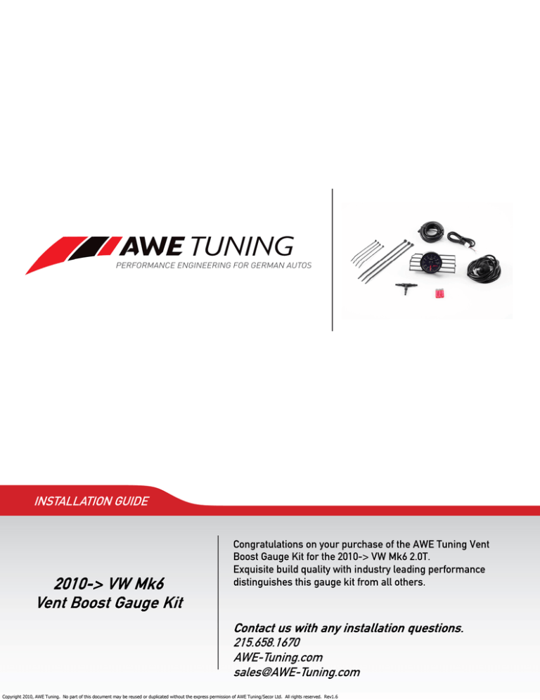
Congratulations on your purchase of the AWE Tuning Vent
Boost Gauge Kit for the 2010-> VW Mk6 2.0T.
Exquisite build quality with industry leading performance
distinguishes this gauge kit from all others.
Contact us with any installation questions.
215.658.1670
AWE-Tuning.com
sales@AWE-Tuning.com
Copyright 2010, AWE Tuning. No part of this document may be reused or duplicated without the express permission of AWE Tuning/Secor Ltd. All rights reserved. Rev1.6
PARTS AND TOOL LIST
1
1
1
1
Preassembled vent and gauge pod
sender unit with wiring harness
gauge wiring harness
buzz filter
1
1
4
6
9
40” length of boost hose
8” length of additional boost hose
red posi-tap connector
medium zip tie
small zip tie
Required tools and materials:
Medium and small flathead screwdrivers
8mm, 10mm, and 13mm sockets and ratchet
Pliers
Torx T20 wrench
X-acto knife/razor blade
1/2” drill bit and drill
Please note that all wiring steps in this manual are documented on a 2010 model year vehicle. Later model
years or models equipped with various other factory options may differ in their wiring schematics. Use a
voltmeter to identify suitable alternative wires if the ones in the images are not present.
Step 1
Open the hood.
Please note that a Boost Tap is required to hook up any type
of boost gauge to this engine. AWE Tuning’s Boost Tap Hose
is pictured at arrow in Figure 1 (note that engine cover has
been removed for photo). This Boost Tap Hose is available at
an additional cost.
Figure 1
Step 2
Remove factory vent assembly by first removing the fuse panel
cover on the end of the dash by the driver’s door.
Push on the back of the vent housing while gently prying from
the front with a wooden or plastic wedge.
Remove the headlight switch by first pushing the knob in while
turning clockwise and then by pulling on the knob to remove the
switch assembly. Once removed, unclip the wiring harness from
the switch.
Figure 2
Copyright 2010, AWE Tuning. No part of this document may be reused or duplicated without the express permission of AWE Tuning/Secor Ltd. All rights reserved. Rev1.6
2
Step 3
Remove the airbox, battery and battery box. The battery sits
inside a large black box to the driver side of the engine under
the hood. Its housing connects to the bottom tray by clips. Also
remove the tray by unbolting its three 10mm head bolts.
Locate the main wiring harness where it comes through the
firewall behind the battery. With a razor, cut the end off one of
the rubber nipples (at arrow in Figure 3)
3 as a pass through for
the boost hose. Lubricate the end of the hose with a little oil
and push through from under the dash inside the car.
Figure 3
Step 4
Prep the vent housing for gauge installation.
Using a small flat tip screwdriver gently pry open the tabs
around the vent housing and remove the housing face as
shown in Figure 4.
4
Figure 4
Step 5
Once the housing face is removed, remove the inner vent fins.
This can be done by squeezing the vent housing slightly and
pulling straight out on the fins.
Figure 5
Step 6
Using a 1/2” drill bit, drill a hole in the passenger side of the
vent housing as shown at arrow in Figure 6.
6
Figure 6
Copyright 2010, AWE Tuning. No part of this document may be reused or duplicated without the express permission of AWE Tuning/Secor Ltd. All rights reserved. Rev1.6
3
Step 7
While holding the housing face, remove the vent fins by pulling
the fins to one side then straight back.
Figure 7
Step 8
Install the preassembled AWE Tuning vent and gauge pod into
the housing face.
Please note that in Step 12 the gauge wiring harness will plug
into the receptacle at arrow in Figure 8.
Figure 8
Step 9
Back in the car under the dash, mount the boost pressure sensor to the fuse panel bracket as shown at arrow in Figure 9.
9
Use two medium zip ties to attach the sensor. Mount the sensor with the inlet pointing downwards and as high up as possible under the dash.
Figure 9
Step 10
Connect one end of the supplied 8 inch piece of boost hose to
the sensor inlet and the other end to the supplied filter, at arrow in Figure 10.
10 Then connect the other end of the filter to the
boost hose previously routed through the fire wall.
Use two small zip ties to secure the boost hose away from
moving parts under the dash. When tightening the zip ties,
ensure that the boost hose is not being crushed.
Figure 10
Copyright 2010, AWE Tuning. No part of this document may be reused or duplicated without the express permission of AWE Tuning/Secor Ltd. All rights reserved. Rev1.6
4
Step 11
Route the connector end of the boost sensor harness up and
out the vent housing opening.
Then route the gauge wiring harness through the headlight
switch opening and out the vent housing opening, making sure
both white connectors are coming out of the vent housing
opening in the dash.
Figure 11
Step 12
Route both white connectors through the drilled hole in the vent
housing and the connect them to the back of the boost gauge.
Plug the 4 pin connector into the right side receptacle when
looking at the gauge from behind (see Step 8). Plug the 3 pin
connector into the middle receptacle on the back of the gauge.
Reinstall the housing face and push the complete gauge, vent,
and housing assembly back into the dashboard, making sure
not to crimp the wiring harnesses.
Figure 12
Step 13
With a razor, carefully strip back the wrap on the headlight
switch wiring harness. Attach the gauge wiring harness to the
headlight switch plug. Follow the directions in Figure 14 to use
the supplied posi-tap connectors and make the following connections (wire position numbers are molded into the headlight
switch connector).
For Constant On Gauge Backlighting:
Switched 12V: Red and Green gauge wires to the Black/Purple
headlight switch wire at position 4.
Constant 12V: White gauge wire to the Red/White headlight
switch wire at position 8.
Ground: Black gauge wire to the Brown headlight switch wire
at position 6.
Figure 13
Figure 14
For Dimmer Knob Controlled Gauge Backlighting:
Switched 12V: Red gauge wire to the Black/Purple headlight
switch wire at position 4.
Dimmer Control: Green gauge wire to gray headlight switch
wire at position 10.
Constant 12V: White gauge wire to the Red/White headlight
switch wire at position 8.
Ground: Black gauge wire to the Brown headlight switch wire
at position 6.
Copyright 2010, AWE Tuning. No part of this document may be reused or duplicated without the express permission of AWE Tuning/Secor Ltd. All rights reserved. Rev1.6
5
Step 14
Reinstall the vehicle’s battery and the engine cover. Ensure all items under the hood are clear from moving objects and start the engine.
You should see ~20 inHg of vacuum reading on the gauge at idle (will vary 3-4 inHg depending on engine
temp). If you see significantly less than 20 inhg of vacuum, check for a kinked or pinched boost gauge
hose.
Complete reassembly of interior.
Troubleshooting Guide
Issue
Remedy
Slow needle response and/or incorrect boost and inHg reading.
Block or kinked boost hose. Check that zip ties
are not too tight or that hose is not being
crimped.
Needle sweeps at start up but sticks at one boost or inHg reading and will not
move.
Block or kinked boost hose. Check that zip ties
are not too tight or that hose is not being
crimped.
Needle sweeps at start up but returns to –30 inHg mark and will not move.
Disconnected or loose Red Wire connection.
Double check installation of that wire.
Needle not at –30 inHg mark when gauge is first received.
Gauge will sweep during initial use and recalibrate itself.
ENJOY
A boost gauge is a valuable tool in determining your car’s state of performance.
Any questions or comments,
please do not hesitate to contact us:
1.888.565.2257
AWE-Tuning.com
sales@AWE-Tuning.com
Copyright 2010, AWE Tuning. No part of this document may be reused or duplicated without the express permission of AWE Tuning/Secor Ltd. All rights reserved. Rev1.6
6
AWE Tuning
2385C Maryland Road
Willow Grove, PA 19090
215.658.1670
sales@AWE-Tuning.com
Thank you for choosing AWE Tuning as your performance automotive parts supplier. Please remember
that a performance car is only as strong as its weakest link. Therefore, it is vital that you maintain your
vehicle to factory specifications.
By installing or using the purchased product, the Consumer accepts this warranty and any specific
Manufacturer warranties enclosed.
Limited Warranty
The following warranty is valid only in the United States.
The Manufacturer’s full warranty applies to all products sold.
Secor Ltd. (AWE Tuning) warrants to the original retail purchaser (Consumer) this product (VW Mk6 Vent
Boost Gauge Kit) against manufacturing defects for one year from date of original purchase.
Upon verification of warranty coverage, AWE Tuning will repair or replace the defective product at their
discretion, without charge. This is the only remedy the Consumer has for any loss or damage, however
arising, due to nonconformity in or defect of the product. This warranty does not cover consequential damage, loss of time or revenues, inconvenience, loss of use of vehicle, damage to the vehicle or components,
or other incidental or indirect damage.
All warranties are void if the product was not installed by a certified auto mechanic, improperly serviced,
modified, or used in a way not intended by the Manufacturer. Use of product in Motorsports or Racing
conditions is grounds for warranty denial. Motorsports and Racing is an inherently abusive operational
condition, and it is impossible to warranty for this type of usage.
The Consumer is responsible for ensuring that the product is installed in a safe and proper manner, and
should cease usage of the product immediately if an unsafe or improper condition is noted. If an unsafe or
improper condition is noted, the Consumer should then immediately contact the facility where the product
was installed or AWE Tuning directly.
Please contact the original place of purchase for any warranty claims or explanations of this document.
Copyright 2010, AWE Tuning. No part of this document may be reused or duplicated without the express permission of AWE Tuning/Secor Ltd. All rights reserved. Rev1.6
7


