Namco - Specialty Product Technologies
advertisement

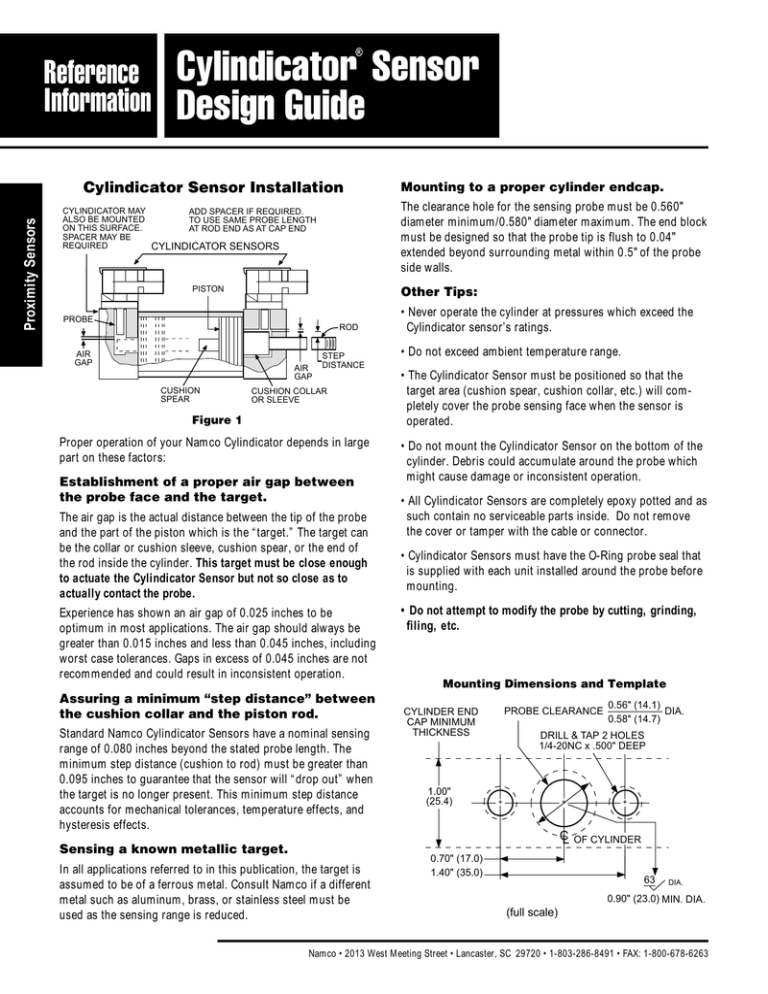
® Reference Information Cylindicator Sensor Design Guide Proximity Sensors Cylindicator Sensor Installation CYLINDICATOR MAY ALSO BE MOUNTED ON THIS SURFACE. SPACER MAY BE REQUIRED The clearance hole for the sensing probe must be 0.560" diameter minimum/0.580" diameter maximum. The end block must be designed so that the probe tip is flush to 0.04" extended beyond surrounding metal within 0.5" of the probe side walls. ADD SPACER IF REQUIRED. TO USE SAME PROBE LENGTH AT ROD END AS AT CAP END CYLINDICATOR SENSORS PISTON Other Tips: PROBE ROD AIR GAP AIR GAP CUSHION SPEAR Mounting to a proper cylinder endcap. STEP DISTANCE CUSHION COLLAR OR SLEEVE Figure 1 Proper operation of your Namco Cylindicator depends in large part on these factors: Establishment of a proper air gap between the probe face and the target. The air gap is the actual distance between the tip of the probe and the part of the piston which is the “target.” The target can be the collar or cushion sleeve, cushion spear, or the end of the rod inside the cylinder. This target must be close enough to actuate the Cylindicator Sensor but not so close as to actually contact the probe. Experience has shown an air gap of 0.025 inches to be optimum in most applications. The air gap should always be greater than 0.015 inches and less than 0.045 inches, including worst case tolerances. Gaps in excess of 0.045 inches are not recommended and could result in inconsistent operation. Assuring a minimum “step distance” between the cushion collar and the piston rod. Standard Namco Cylindicator Sensors have a nominal sensing range of 0.080 inches beyond the stated probe length. The minimum step distance (cushion to rod) must be greater than 0.095 inches to guarantee that the sensor will “drop out” when the target is no longer present. This minimum step distance accounts for mechanical tolerances, temperature effects, and hysteresis effects. Sensing a known metallic target. In all applications referred to in this publication, the target is assumed to be of a ferrous metal. Consult Namco if a different metal such as aluminum, brass, or stainless steel must be used as the sensing range is reduced. • Never operate the cylinder at pressures which exceed the Cylindicator sensor’s ratings. • Do not exceed ambient temperature range. • The Cylindicator Sensor must be positioned so that the target area (cushion spear, cushion collar, etc.) will completely cover the probe sensing face when the sensor is operated. • Do not mount the Cylindicator Sensor on the bottom of the cylinder. Debris could accumulate around the probe which might cause damage or inconsistent operation. • All Cylindicator Sensors are completely epoxy potted and as such contain no serviceable parts inside. Do not remove the cover or tamper with the cable or connector. • Cylindicator Sensors must have the O-Ring probe seal that is supplied with each unit installed around the probe before mounting. • Do not attempt to modify the probe by cutting, grinding, filing, etc. Mounting Dimensions and Template PROBE CLEARANCE CYLINDER END CAP MINIMUM THICKNESS 1.00" (25.4) 0.56" (14.1) DIA. 0.58" (14.7) DRILL & TAP 2 HOLES 1/4-20NC x .500" DEEP + + CL 0.70" (17.0) 1.40" (35.0) + OF CYLINDER 63 DIA. 0.90" (23.0) MIN. DIA. (full scale) Namco • 2013 West Meeting Street • Lancaster, SC 29720 • 1-803-286-8491 • FAX: 1-800-678-6263 100 NOTE: If a cylinder is mechanically restrained from going full stroke — no target will be present for the switch to detect (no switch output). Target End View Smaller diameter targets have less metal in the sensing field at a constant air gap. Loss of stroke-to-go is more pronounced on smaller bore cylinders as air gap increases. PROBE AIR GAP Proximity Sensors “Stroke To Go” vs. “Air Gap” “Stroke To Go” The amount of stroke remaining in the cylinder after the Cylindicator Sensor activates. SMALL TARGET LARGE TARGET Switch Actuated PROBE AIR GAP = 0.025" RADIO FREQUENCY CONE Recommended nominal air gap distance provides the stated maximum stroke to go. TARGET STROKE TO GO PROBE Switch Actuated AIR GAP = 0.045" Variations from the recommended nominal air gap distance results in loss of stroke to go. TARGET LESS STROKE TO GO PROBE AIR GAP > 0.045" Switch Probably Not Actuated Increased variations from the recommended nominal air gap distance results in little or no stroke to go and possible erratic operation. TARGET LITTLE OR NO STROKE TO GO *Loss of stated maximum stroke to go can prevent the proximity sensor from activating in plant equipment and tools with positive stops. 2013 West Meeting Street • Lancaster, SC 29720 1-803-286-8491 • FAX: 1-800-678-6263 www.namcocontrols.com For technical assistance, call 1-800-NAMTECH 101


