BUY AMERICAN ACT OF 2009 COMPLIANT
FINELITE
Integrated Sensor - Occupancy
Date
Project
Type
Comments
DESCRIPTION
Integrated Occupancy Sensor is integrated in the luminaire in a clean and seamless manner. Easy to
specify and commission, this solution simplifies installation, maximizes user satisfaction, and saves
energy. The Occupancy Sensor integrates with standard on/off or bi-level switching ballasts to provide
for single-level or dual-level occupancy-based control within a designated controlled zone.
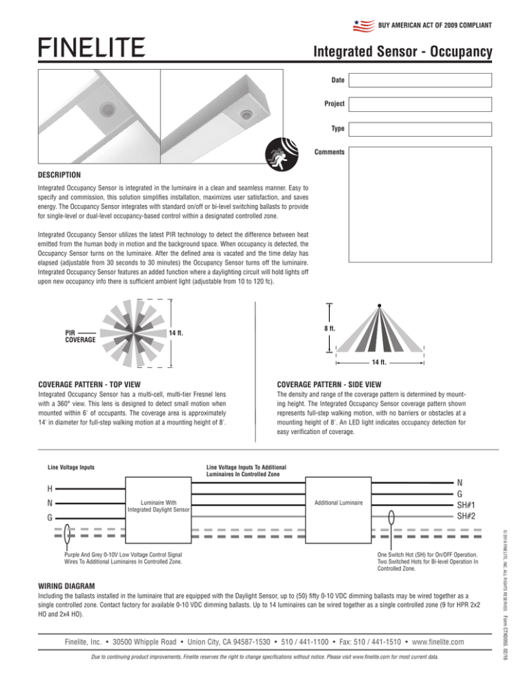
Integrated Occupancy Sensor utilizes the latest PIR technology to detect the difference between heat
emitted from the human body in motion and the background space. When occupancy is detected, the
Occupancy Sensor turns on the luminaire. After the defined area is vacated and the time delay has
elapsed (adjustable from 30 seconds to 30 minutes) the Occupancy Sensor turns off the luminaire.
Integrated Occupancy Sensor features an added function where a daylighting circuit will hold lights off
upon new occupancy info there is sufficient ambient light (adjustable from 10 to 120 fc).
PIR
COVERAGE
8 ft.
14 ft.
14 ft.
COVERAGE PATTERN - TOP VIEW
COVERAGE PATTERN - SIDE VIEW
Integrated Occupancy Sensor has a multi-cell, multi-tier Fresnel lens
with a 360° view. This lens is designed to detect small motion when
mounted within 6' of occupants. The coverage area is approximately
14' in diameter for full-step walking motion at a mounting height of 8'.
The density and range of the coverage pattern is determined by mounting height. The Integrated Occupancy Sensor coverage pattern shown
represents full-step walking motion, with no barriers or obstacles at a
mounting height of 8'. An LED light indicates occupancy detection for
easy verification of coverage.
Line Voltage Inputs
Line Voltage Inputs To Additional
Luminaires In Controlled Zone
N
G
SH#1
SH#2
H
N
Luminaire With
Integrated Daylight Sensor
Additional Luminaire
G
One Switch Hot (SH) for On/OFF Operation.
Two Switched Hots for Bi-level Operation In
Controlled Zone.
WIRING DIAGRAM
Finelite, Inc. • 30500 Whipple Road • Union City, CA 94587-1530 • 510 / 441-1100 • Fax: 510 / 441-1510 • www.finelite.com
Due to continuing product improvements, Finelite reserves the right to change specifications without notice. Please visit www.finelite.com for most current data.
Form CTK0055. 02/16
Including the ballasts installed in the luminaire that are equipped with the Daylight Sensor, up to (50) fifty 0-10 VDC dimming ballasts may be wired together as a
single controlled zone. Contact factory for available 0-10 VDC dimming ballasts. Up to 14 luminaires can be wired together as a single controlled zone (9 for HPR 2x2
HO and 2x4 HO).
© 2016 FINELITE, INC. ALL RIGHTS RESERVED.
Purple And Grey 0-10V Low Voltage Control Signal
Wires To Additional Luminaires In Controlled Zone.
BUY AMERICAN ACT OF 2009 COMPLIANT
FINELITE
Integrated Sensor - Occupancy
COMMISSIONING ADJUSTMENTS
The time delay and light level adjustments are easily made on the sensor. The time delay can be adjusted for
30 seconds to 30 minutes and comes pre-set from the factory at 15 minutes. The light level adjustment is
pre-set at maximum, so HPR luminaires will turn on with occupancy under any ambient lighting condition.
R
FS-205 Front
RJ45 jack
Connecting cable
24 AWG, 80˚C, 300V
Fresnel lens
Beauty ring
MAX
MIN
MAX
MIN
Light Level
Time Delay
FS-205 Back
Time delay
Light level
T
L
FS-305
Factory Settings
1 9/64"
1 9/32"
Time Delay
(30sec-30min)
2 7/20"
1 19/50"
Due to continuing product improvements, Finelite reserves the right to change specifications without notice. Please visit www.finelite.com for most current data.
Form CTK0055. 02/16
Finelite, Inc. • 30500 Whipple Road • Union City, CA 94587-1530 • 510 / 441-1100 • Fax: 510 / 441-1510 • www.finelite.com
© 2016 FINELITE, INC. ALL RIGHTS RESERVED.
Light Level


