Datasheet Micropack Rectifiers
advertisement

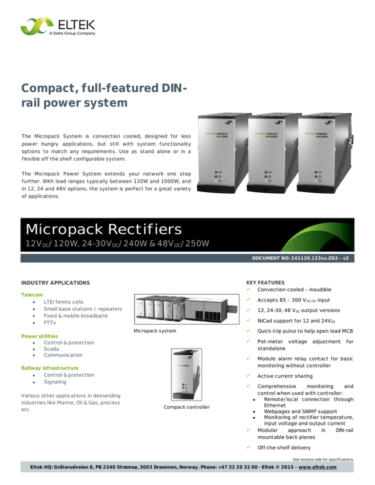
Compact, full-featured DINrail power system The Micropack System is convection cooled, designed for less power hungry applications, but still with system functionality options to match any requirements. Use as stand alone or in a flexible off the shelf configurable system. The Micropack Power System extends your network one step further. With load ranges typically between 120W and 1000W, and in 12, 24 and 48V options, the system is perfect for a great variety of applications. Micropack Rectifiers 12VDC/120W, 24-30VDC/240W & 48VDC/250W DOCUMENT NO: 241120.123xx.DS3 – v2 INDUSTRY APPLICATIONS KEY FEATURES ü Convection cooled – inaudible Telecom LTE/femto cells • Small base stations / repeaters • Fixed & mobile broadband • FTTx • Power utilities • Control & protection • Scada • Communication Micropack system Railway infrastructure Control & protection • Signaling • Various other applications in demanding industries like Marine, Oil & Gas, process etc. ü Accepts 85 – 300 VAC/DC input ü 12, 24-30, 48 VDC output versions ü NiCad support for 12 and 24VDC ü Quick-trip pulse to help open load MCB ü Pot-meter voltage adjustment for standalone ü Module alarm relay contact for basic monitoring without controller ü Active current sharing Comprehensive monitoring and control when used with controller: Remote/local connection through • Ethernet Webpages and SNMP support • Monitoring of rectifier temperature, • input voltage and output current ü Modular approach in DIN-rail mountable back planes ü Compack controller ü Off-the-shelf delivery See reverse side for specifications Eltek HQ: Gråterudveien 8, PB 2340 Strømsø, 3003 Drammen, Norway. Phone: +47 32 20 32 00 - Eltek © 2015 – www.eltek.com Micropack Rectifiers 12VDC/120W, 24-30VDC/240W & 48VDC/250W Model 12V / 120W 24V / 240W 48V / 250W 241120.300 241120.200 241120.100 Part number INPUT DATA 85 - 300 VAC/DC 1) Voltage range Voltage range (nominal) 185 - 275 VAC/DC 1) 130 - 275 VAC/DC Frequency 0 - 66 Hz Maximum current, 230V input / overall (boost) 0.6 A / 2.0 A Maximum earth leakage current Power Factor THD (@ 230 VAC) Protection 1) 1.2 A / 2.0 A 1.2 A / 1.9 A 2.0 mA (@ 250VAC/50Hz) 0.97 (@ 70 - 100 % load) 0.98 (@ 55 - 100 % load) 0.98 (@ 50 - 100 % load) < 5 % (@ 80 - 100 % load) < 5 % (@ 50 - 100 % load) < 5 % (@ 50 - 100 % load) Varistor for transient protection, fuse in both lines (2x 2.0 A), shutdown above 300 VAC/DC OUTPUT DATA Default voltage 13.6 VDC 27.2 VDC 53.5 VDC Voltage range 10.7 - 18.0 VDC 21.5 - 36 VDC 43.5 - 57.6 VDC Voltage range without controller 10.7 - 15.0 VDC 21.5 - 30 VDC 43.5 - 57.6 VDC 6-7 12 - 15 24 2) 2) - 120 W / 160 W 240 W / 315 W 250 W / - 10 A / 15 A / 55 A 10 A / 15 A / 55 A 5A/-/- # Pb cell supported (1.8 - 2.4 VDC/cell) # NiCad cell supported (1.05 - 1.65 VDC/cell) Max power, nominal / 60s boost Max current, @12/24/48VDC / boost / QT3) 10 - 11 20 - 22 Current sharing ±5% of maximum current from 10 to 100% load Static voltage regulation ±0.5% from 10% to 100% load and nominal input Dynamic voltage regulation ± 5 % < 10ms, load step 10% to 90% or opposite at nominal output voltage Hold-up time, default voltage and full power Rippel and noise, 30 MHz b.w. / psophometric Protection 20 ms, VOUT > 10.7 VDC 20 ms, VOUT > 21.5 VDC 20 ms, VOUT > 43 VDC < 200 mVPP / 5 mVRMS < 200 mVPP / 5 mVRMS < 150 mVPP / 2 mVRMS Overvoltage shutdown, short circuit proof, high temperature, hot plug-in inrush current limiting, fuse OTHER SPECIFICATIONS Efficiency @ nominal input/output, peak/range 89.5% / >88%, 50-100% load 93.0% / >92%, 50-100% load 93.6% / >93%, 50-100% load Isolation 3.0 kVAC – input and output, 1.5 kVAC – input earth, 0.5 kVDC – output earth Alarms: Red LED 'on' Low mains shutdown, High and low temperature shutdown, Rectifier Failure, Overvoltage shutdown on output, Fan failure, Low voltage alarm, CAN bus failure Warnings: Yellow LED 'on' Rectifier in power derate mode, Remote battery current limit activated, Input voltage out of range, flashing at overvoltage Normal (module running): Green LED 'on' Alarm output (isolated) NO (+positive terminal), COM (-negative terminal). 60 V / 100 mA max MTBF (Telcordia SR-332 Issue I method III (a)) >480 000h (@TAMBIENT= 25°C) >480 000h (@TAMBIENT= 25°C) >500 000h (@TAMBIENT= 25°C) Operating temperature (5 - 95% RH non-cond.) Output power de-rates above temp / to -40 to +70°C [-40 — +158°F] +55°C / 50W @ +70°C -40 to +60°C [-40 to +142°F] +45°C / 80W @ +60°C -40 to +75°C [-40 to +167°F] +55°C / 140W @ +75°C Storage temperature -40 to +85°C (-40 to +185°F), humidity 0 - 99% RH non-condensing Dimensions[WxHxD] / Weight 39.0 x 88.5 x 149mm [1.54 x 3.48 x 5.87"] / 0.5 kg [1.1 lbs] DESIGN STANDARDS Electrical safety UL 60950-1, EN 60950-1, CSA 22.2 EMC ETSI EN 300 386 V.1.3.2 EN 61000-6-1 / -2 / -3 / -4 / -54) Mains Harmonics EN 61000-3-2 Environment ETSI EN 300 019: 2-1 (Class 1.2), 2-2 (Class 2.3) & 2-3 (Class 3.2) ETSI EN 300 132-2 2002/95/EC (RoHS) & 2002/96/EC (WEEE) Marine compliance (EMC class B with AC filter) DnV Rules for Classification of Ships, High Speed & Light Craft and DnV Offshore Standards 1) DC support for 241120.200 with primary FW 404088.009 (from HW revision 1.2) and 241120.100 from HW revision 2 2) 11/22 cells with max boost voltage 1.636 VDC/cell 3) Quick-Trip function, if VOUT = 5 VDC a 35 ms current pulse is generated to help trip fuse/MCB on short circuited branch 4) Only 12V and 24V Eltek HQ: Gråterudveien 8, PB 2340 Strømsø, 3003 Drammen, Norway. Phone: +47 32 20 32 00 - Eltek © 2015 – www.eltek.com


