FM4-176L-S6E2GM QUICK START GUIDE
FM4 S6E2G-SERIES PIONEER KIT
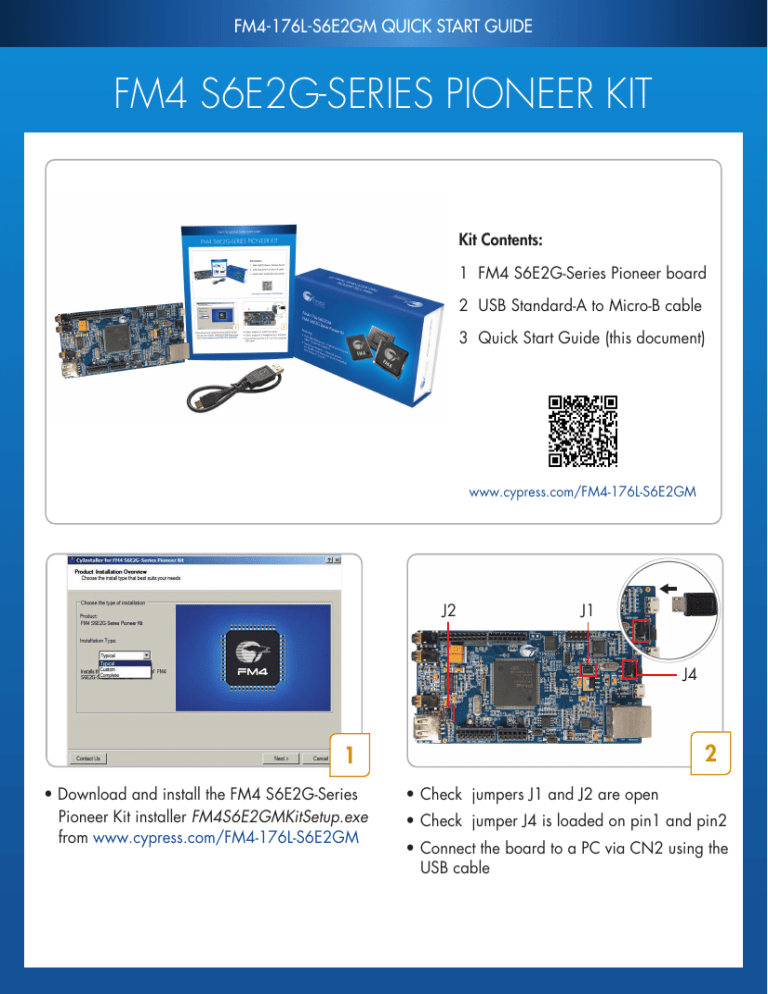
Kit Contents:
1 FM4 S6E2G-Series Pioneer board
2 USB Standard-A to Micro-B cable
3 Quick Start Guide (this document)
www.cypress.com/FM4-176L-S6E2GM
J2
J1
J4
2
1
• Download and install the FM4 S6E2G-Series
Pioneer Kit installer FM4S6E2GMKitSetup.exe
from www.cypress.com/FM4-176L-S6E2GM
• Check jumpers J1 and J2 are open
• Check jumper J4 is loaded on pin1 and pin2
• Connect the board to a PC via CN2 using the
USB cable
FM4-176L-S6E2GM QUICK START GUIDE
3
• Launch the Serial Port Viewer Tool from
Start > All Programs > Cypress >
Serial Port Viewer Tool
• Click on the Serial Port Viewer icon in
the notification area of the taskbar and
select FM-Link/CMSIS-DAP Cypress FM
Communications Port
5
4
• Configure the baud rate as 115200
• Click the Disconnected button to connect
• Press Enter on your PC keyboard to run the
board test demo
6
• Key in 5 and press Enter to change the RGB LED • Use IAR Embedded Workbench or Keil uVision
(LED4) color from Red to Green to Blue. For more
to develop code examples on this kit
information on the test procedures, refer to the kit
user guide
FM4-176L-S6E2GM QUICK START GUIDE
FM4 S6E2G-Series Pioneer Board Details
1 25 2
24
3
4
23
5
22
6
21
7
8
9
20
19
10
18
17
16
15 14 13 12 11
1.
Cypress FM4 S6E2GM8J0A MCU
13. User button (SW2)
2.
4-Mb SRAM
14. Reset button (SW1)
3.
10-pin JTAG connector (CN1)
15. Accelerometer
4.
Multicon Interface connector (CN12)
16. Additional GPIO headers (CN15-CN18)
MB9F312K Programmer and Debugger
17. RGB LED (LED4)
(CMSIS-DAP) (CN2)
18. USB host connector (CN14)
6.
Power supply source select (J4)
19. Programming mode jumper of S6E2GM (J2)
7.
Serial programming mode select (J3)
20. Line-in jack (CN6)
8.
Programming mode jumper of MB9F312K (J1) 21. Stereo codec
9.
USB device connector (CN3)
5.
22. Microphone jack (CN11)
10. Ethernet PHY and RJ45 connector (CN4)
23. Headphone jack (CN5)
11. Phototransistor
24. ArduinoTM interface (CN7-CN10)
12. 32-Mb Quad-SPI NOR Flash
25. Additional-pins for Multicon Interface connector
(CN13)
FM4-176L-S6E2GM QUICK START GUIDE
FM4 S6E2G-SERIES PIONEER KIT
FM4 S6E2G-Series Pioneer Board Details
P10
PB3
P1B
PB4
P1C
NC
3V3
GND
NC
NC
P94
P95
NC
NC
NC/NC
5V0/IOREF
INTX/RESET
3V3/3.0V
5V0/5V
GND/GND
GND/GND
5V0/Vin
P11/A0
P12/A1
P13/A2
P16/A3
P14/A4
P15/A5
PB0/SCL
P17/SDA
AREF/AREF
GND/GND
P42/D13
P40/D12
P41/D11
P4D/D10
P4E/D9
PF2/D8
P71
PF1
PF0
P3C
P37
P36
P35
P34
3V3
GND
PF3/D7
P45/D6
P44/D5
PF4/D4
P43/D3
PF7/D2
PF6/D1
PF5/D0
P42
GND
P3B
P40
CN13_2
P33
P32
P31
P30
P0A
P52
P51
P50
P41
3V3
P3A
P44
CN13_1
Arduino interface
FM4 S6E2G-Series Pioneer board
NC - Not Connected
For the latest information about this kit, visit www.cypress.com/FM4-176L-S6E2GM
© 2016 Cypress Semiconductor Corporation. All rights reserved.
All trademarks or registered trademarks referenced herein are the property of their respective owners.
001-99193 Rev.*C


