GPD
MODEL
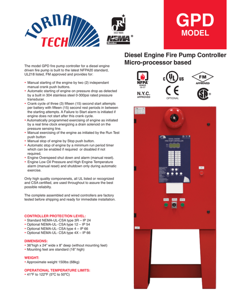
The model GPD fire pump controller for a diesel engine
driven fire pump is built to the latest NFPA20 standard,
UL218 listed, FM approved and provides for:
• Manual starting of the engine by two (2) independant
manual crank push buttons.
• Automatic starting of engine on pressure drop as detected
by a built in 304 stainless steel 0-300psi rated pressure
transducer.
• Crank cycle of three (3) fifteen (15) second start attempts
per battery with fifteen (15) second rest periods in between
the starting attempts. A Failure to Start alarm is initiated if
engine does not start after this crank cycle.
• Automatically programmed exercising of engine as initiated
by a real time clock energizing a drain solenoid on the
pressure sensing line.
• Manual exercising of the engine as initiated by the Run Test
push button
• Manual stop of engine by Stop push button.
• Automatic stop of engine by a minimum run period timer
which can be enabled if required or disabled if not
required.
• Engine Overspeed shut down and alarm (manual reset).
• Engine Low Oil Pressure and High Engine Temperature
alarm (manual reset) and shutdown only during automatic
exercise.
Only high quality componenets, all UL listed or recognized
and CSA certified, are used throughout to assure the best
possible reliabilty.
The complete assembled and wired controllers are factory
tested before shipping and ready for immediate installation.
CONTROLLER PROTECTION LEVEL:
• Standard NEMA-UL-CSA type 3R – IP 24
• Optional NEMA-UL- CSA type 12 – IP 54
• Optional NEMA-UL- CSA type 4 – IP 66
• Optional NEMA-UL- CSA type 4X – IP 66
DIMENSIONS:
• 36”high x 24” wide x 8” deep (without mounting feet)
• Mounting feet are standard (16” high)
WEIGHT:
• Approximate weight 150lbs (68kg)
OPERATIONAL TEMPERATURE LIMITS:
• 41ºF to 122ºF (5ºC to 50ºC)
Diesel Engine Fire Pump Controller
Micro-processor based
N.Y.C.
APPROVED
OPTIONAL
GPD
MODEL
Diesel Engine Fire Pump Controller
Micro-processor based
STANDARD FEATURES:
• Two independent fully automatic battery chargers rated for
10 A. continuous charge, 12 or 24 VDC c/w AC input filter,
current limiter, over current shutoff, 500 mA trickle charge,
dead cell detection, low battery voltage alarm.
• 304 stailess steel pressure transducer raited for 0-300 PSI
• 4’’ bell
• Individual manual crank push buttons (2)
• Individual battery circuit breakers
• Master selector switch (manual-off-auto)
• Run period timer for automatic stop
• Sequential start timer
• Run test push button
• Provision for remote start push button
• Provision for deluge valve start
• Drain solenoid valve for weekly exercise
• System overpressure adjustable setting and alarm contact
(DPDT) for use with pressure limiting device supplied on
diesel engine
• Option for terminal connection (301-302) for ECM diesel
engine
• Remote alarm circuits rated 8A. 220VAC for
- Engine run (DPDT).
- Master Selector Switch in Off or Manual (1 N/O).
- Master Selector Switch in Auto (1 N/O).
- Engine Trouble (1 DPDT).
- Overspeed, fail to start, low oil pressure,
high coolant temperature, fail when running
• Controller trouble (1 DPDT):
- Battery 1 or 2 failure, charger 1 or 2 failure, pressure
line failure
• Pump room alarms (1 DPDT):
- Low suction, low fuel level, water reservoir low,
water reservoir empty, low pump room temperature,
high fuel level, AC failure
• Pressure and event recorder with thermal printer supplied
as standard.
OPTIONAL FEATURES:
Type A: Individual engine alarm contacts (DPDT)
Type B: Pump room alarm contacts (DPDT)
Type C: Operational modifications
Type D: Miscellaneous
Built to latest NFPA20 STANDARD
Montreal, Canada
Cut-out
Cut-in
AC Power
On
System
Main Switch
in Auto
Battery #1
Failure
Battery #2
Failure
Charger #1
Failure
Charger #2
Failure
Engine
Low Oil Pressure
Engine
High Temp.
Engine
Overspeed
Engine
Run
Engine
Fail to Start
Fail when
Running
Pump Room
Alarm
Deluge Valve /
Remote Start
Weekly
Test
Controller
Trouble
OPERATING INSTRUCTIONS
NORMAL OPERATION
Turn main switch to AUTO position
and close door.
Engine may start if water pressure
is below cut-in setting.
EMERGENCY START
Open or break switch cover
and turn main switch to MANUAL
position. Press either or both
MANUAL CRANK buttons until
engine starts.
Cut-out
Cut-in
Digital display
• Individual charger voltmeter and ammeter readout
• Individual charger mode indication
• Individual cut-in, cut-out and system pressure readout
Annunciator and display panel
• 16 annunciator points c/w super bright red led
Pressure setting field adjustments
• Accessible with main door closed
• Live settings adjustments visible on display
Manual operators
• Lamp test / silence push button
• Run test push button
• Print push button
• Paper feed push button
STOPPING
If all starting conditions
have been eliminated, press
the STOP button.
If not, turn main switch
to OFF position.
RUN TEST START AND STOP
To start, turn main switch to AUTO position
and press RUN TEST button. Engine will start
due to an artificial pressure drop created
by the solenoid valve.
To stop, press STOP button or turn main
switch to OFF position.
HOW TO ORDER:
GPD - Negative or Positive ground - 12 or 24 VDC - Floor or Wall mounted - BCE - 10 - options
Ex.: GPD N
12
F
- BCE - 10 - options
Tornatech inc., 7075, Place Robert-Joncas, # 132, Montreal, Quebec, Canada H4M 2Z2
Tel.: + 1 514 334 0523 + 1 800 363 8448 (Canada & U.S.A.) Fax: + 1 514 334 5448
E-mail: tornatech@tornatech.com
www.tornatech.com
GPD-BRO-001/E Rev.2
Subject to modification without notice
All rights reserved. Printed in Canada


