Lin Eng motor guide
advertisement
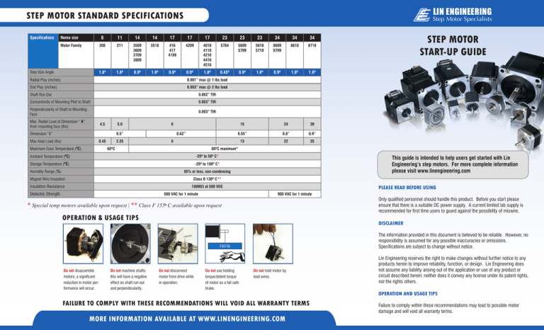
LIN ENGINEERING STEP MOTOR STANDARD SPECIFICATIONS Specifications 8 11 14 14 17 17 17 23 23 23 34 34 34 208 211 3509 3609 3709 3809 3518 416 417 4109 4209 4018 4118 4218 4418 4518 5704 5609 5709 5618 5718 8609 8709 8618 8718 1.8º 1.8º 0.9º 1.8º 0.9º 0.9º 1.8º 0.45º 0.9º 1.8º 0.9º 1.8º 1.8º Nema size Motor Family Step Size Angle Step Motor Specialists Radial Play (inches) 0.001” max @ 1 lbs load End Play (inches) 0.003” max @ 2 lbs load Shaft Run Out 0.002” TIR Concentricity of Mounting Pilot to Shaft 0.003” TIR Perpendicularity of Shaft to Mounting Face 0.003” TIR Max. Radial Load at Dimension “ K” from mounting face (lbs) 4.5 5.0 Dimension “K” 6 0.5” Max Axial Load (lbs) 0.45 Maximum Case Temperature (ºC) 2.25 0.62” 24 39 0.55” 0.8” 0.9” 13 22 25 6 60ºC 80ºC maximum* Ambient Temperature (ºC) -20º to 50º C* Storage Temperature (ºC) -20º to 100º C* Humidity Range (%) 15 This guide is intended to help users get started with Lin Engineering’s step motors. For more complete information please visit www.linengineering.com 85% or less, non-condensing Magnet Wire Insulation STEP MOTOR START-UP GUIDE Class B 130º C** Insulation Resistance 100MΩ at 500 VDC Dielectric Strength 500 VAC for 1 minute PLEASE READ BEFORE USING 900 VAC for 1 minute * Special temp motors available upon request | ** Class F 155º C available upon request OPERATION & USAGE TIPS DISCLAIMER The information provided in this document is believed to be reliable. However, no responsibility is assumed for any possible inaccuracies or omissions. Specifications are subject to change without notice. 100 lb Do not disassemble motors; a significant reduction in motor performance will occur. Do not machine shafts; this will have a negative effect on shaft run out and perpendicularity. Only qualified personnel should handle this product. Before you start please ensure that there is a suitable DC power supply. A current limited lab supply is recommended for first time users to guard against the possibility of miswire. Do not disconnect motor from drive while in operation. Do not use holding torque/detent torque of motor as a fail safe brake. Do not hold motor by lead wires. FAILURE TO COMPLY WITH THESE RECOMMENDATIONS WILL VOID ALL WARRANTY TERMS MORE INFORMATION AVAILABLE AT WWW.LINENGINEERING.COM Lin Engineering reserves the right to make changes without further notice to any products herein to improve reliability, function, or design. Lin Engineering does not assume any liability arising out of the application or use of any product or circuit described herein; neither does it convey any license under its patent rights, nor the rights others. OPERATION AND USAGE TIPS Failure to comply within these recommendations may lead to possible motor damage and will void all warranty terms. LIN ENGINEERING LEAD WIRE COLOR CODE Step Motor Specialists 1 2 3 4 Color Code 1 Red Blue Green Black Color Code 2 Brown Orange Red Yellow Color Code 3 Red Bipolar Driver A A B B 1 2 3 4 5 6 Color Code 1 Red White Blue Green Yellow Black Color Code 2 Brown Black Orange Red White Yellow Color Code 3 Red Black Green White A A B B Bipolar Drive Half Coil Connection Unipolar Drive Color Code 1 A 1 2 Blue Red White Stripe Red Color Code 3 Red Bipolar Drive Parallel Connection Unipolar Drive A/C Comm Phase B B C B By following a series of easy steps, the below charts can be used to properly connect your motor to your drive. Determine how many lead wires your motor has 4, 6, or 8 wires. Locate the proper box below. Next, examine the color code of the lead wires on your motor; find the row of colors that match your wires, this is your “Color Code”. You will have either Code 1, Code 2, or Code 3. For example, if you have 4 wires and the wires are Red, Blue, Green, and Black, your Color Code is 1. Next. Connect the proper color to the appropriate terminal on your drive. If you have a Bipolar drive, the terminal on your drive will be labeled A, A, B, B. 1 2 Green White Stripe 3 B A 4 B B B/D Comm 4 D 5 Phase B For example, if using the above 4 wire motor with Color Code 1, the Red wire would be connected to A, Blue connected to A, Green connected to B, and Black connected to B. If you have a Unipolar drive, the terminal will be labeled A, B, C, D and A/C Common, B/D Common (or Comm.) 6 Notes: Color Code 2 Bipolar Drive Series Connection A 3 White Stripe Yellow 3 4 Blue Red Red White Stripe Black White Stripe Red White Stripe White Stripe A 5 6 Green Black White Stripe White Stripe Yellow Orange Black Green A Black 8 Green Black 1 Black 3 2 Yellow 4 Orange� White Stripe White Stripe Green� Yellow White Stripe White Stripe B Indicates that two particular wires are connected to each other, but not the driver. Indicates that two particular wires are connected to each other, and then connected to the indicated terminal on the drive. In this example, two wires are connected together, then both wired to terminal A on the drive. B A A B B A C B D A/C Comm Indicates that the particular wire is not connected to the drive. 7 Phase A 8 LEAD WIRES White Stripe A CONNECTION INSTRUCTIONS White Stripe Red A Bipolar Drive Series� Connection Green Green White Stripe Lin Engineering step motors are available with either 2-coil Bipolar, or 4-coil Unipolar windings. Bipolar motors have 4 leads, while unipolar motors have 6 leads. Additionally, some motors are designed with 8 leads, so they may be connected in a variety of ways. Phase A 6 LEAD WIRES Red 2 CABLES & CONNECTORS Phase A 1 4 LEAD WIRES B/D Comm 5 7 6 8 Phase B 1990 Russell Avenue, Santa Clara, CA 95054 Tel: 408.919.0200 Fax: 408.919.0201 www.linengineering.com


