CARRILLO
The Choice Connection
ELECTRONICALLY REPRINTED FROM NOVEMBER 2003
Eliminate
Connecting
Rod
Failures
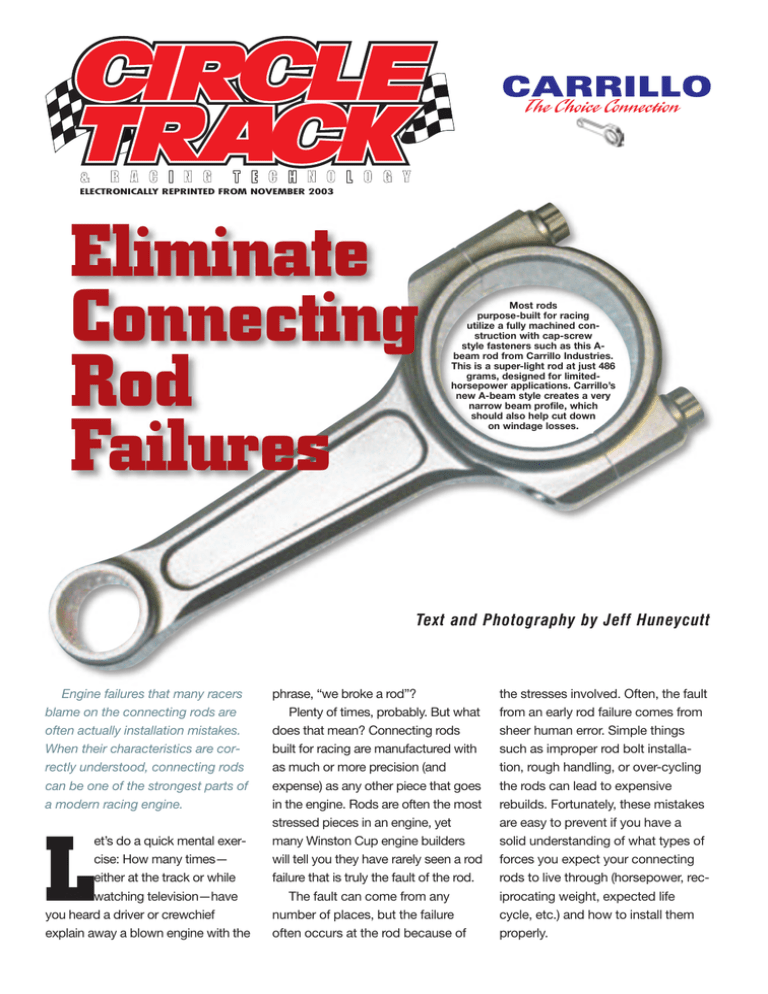
Most rods
purpose-built for racing
utilize a fully machined construction with cap-screw
style fasteners such as this Abeam rod from Carrillo Industries.
This is a super-light rod at just 486
grams, designed for limitedhorsepower applications. Carrillo’s
new A-beam style creates a very
narrow beam profile, which
should also help cut down
on windage losses.
Text and Photography by Jeff Huneycutt
Engine failures that many racers
blame on the connecting rods are
often actually installation mistakes.
When their characteristics are correctly understood, connecting rods
can be one of the strongest parts of
a modern racing engine.
L
et’s do a quick mental exercise: How many times—
either at the track or while
watching television—have
you heard a driver or crewchief
explain away a blown engine with the
phrase, “we broke a rod”?
Plenty of times, probably. But what
does that mean? Connecting rods
built for racing are manufactured with
as much or more precision (and
expense) as any other piece that goes
in the engine. Rods are often the most
stressed pieces in an engine, yet
many Winston Cup engine builders
will tell you they have rarely seen a rod
failure that is truly the fault of the rod.
The fault can come from any
number of places, but the failure
often occurs at the rod because of
the stresses involved. Often, the fault
from an early rod failure comes from
sheer human error. Simple things
such as improper rod bolt installation, rough handling, or over-cycling
the rods can lead to expensive
rebuilds. Fortunately, these mistakes
are easy to prevent if you have a
solid understanding of what types of
forces you expect your connecting
rods to live through (horsepower, reciprocating weight, expected life
cycle, etc.) and how to install them
properly.
E l i m i n a t e C o n n e c t i n g R o d Fa i l u r e
CONSTRUCTION Since almost all
forms of stock car racing limit rods
to stainless steel in the interest of
cost containment, this article will
concentrate only on processes
involving that material. For stainless
rods, there are several options for
construction, namely forged, powder
forged, billet, and fully machined.
Powder-forged rods are used
almost exclusively in OEM applications. Powder forging allows for a
cheap, fairly rugged rod, but it isn’t
the quality of a standard forging. You
will be hard-pressed to find a
purpose-built racing rod that has
been powder forged. However, if you
are racing a strictly stock class that
doesn’t allow aftermarket rods, this
might be what you are stuck with. As
long as they are balanced, you aren’t
likely to exceed a powder-forged
rod’s horsepower limitations in a
stock engine.
Next up the durability scale are
forged rods. “The advantage of forging is that steel, just like wood, has a
grain direction,” explains Jack
Sparks of Carrillo Industries. “When
put in the proper position, it
enhances the fatigue properties of
the part. Forging a rod allows you to
manipulate the grain direction in the
steel. The optimum is to have longitudinal grain flow (up and down) in
the blade area and cylindrical grain
flow around the big end.”
The problem with a forged rod
also comes from the act of forging.
The forging process leaves an inconsistent, rough surface on the rod.
This roughness creates a multitude
of stress points on the rod. “If you
disregard the fasteners, most failures in a connecting rod are gener-
ated from some sort of inclusion or
stress riser on the surface,” Sparks
explains. “It’s like putting a notch in
a coat hanger. When you bend it, it
is going to break at the notch.”
A billet rod is created by literally
machining the rod out of a solid
chunk of metal. The machining
process creates a smooth surface
that is (unless there is a problem in
the manufacturing process or simply
a bad design) free of surface inclusions. By avoiding the forging
process altogether you have avoided
a weakness, but you haven’t been
able to take advantage of strength
by influencing the grain flow.
Enter what is commonly known as
the “fully machined” rod. This process
produces the strongest rod (gauging
material strength only) by taking the
best traits of the forging and billet
processes and combining them. A
fully machined rod starts out as a
large forging (over six pounds in the
case of most of Carrillo’s rods) and
then is machined into its final form
much like a billet rod. This produces a
rod that has the optimum grain structure of a forging along with the
smooth exterior that you find in billet
pieces. It’s the best of both worlds.
FASTENERS Fasteners, no matter
what type, are the greatest weakness in a connecting rod. However, if
installed correctly, most fasteners
from quality manufacturers are
capable of handling the stresses
they are designed for. Before we talk
about correct installation, we first
need to have an understanding of
what’s out there.
The fasteners used to hold the
two pieces of the big end of the rod
Although it can be done with different
styles of calipers, a dedicated bolt
stretch gauge is designed to do its job
while the rod is installed in the engine.
It will make your life easier.
together come in two designs. Thrubolt designs have a complete bolt
and nut to clamp the rod together. A
cap-screw design eliminates the nut,
instead utilizing threads in the rod for
the bolt to thread into. A thru-bolt
design requires flat faces to be cut
into the big end of the rod for each
bolt (one for the head of the bolt and
one for the nut). Eliminating the flat
for the nut makes the cap screw that
much stronger. Additionally, threading the bolt directly into the body of
the rod also helps rigidity.
them they need to be checking
stretch, and then it won’t matter if they
are using peanut butter as a lubricant.”
Of course, Sparks admits that
peanut butter makes a much better
sandwich than it does a lubricant,
but he makes his point. Take, for
example, moly-based lubes, which
are most commonly used for rod
bolts. Moly lubes have a metallic
base. It’s good because it doesn’t
come off easily, but that also means
that every time you pre-fit the rod
bolts you are polishing those
threads, and every time you add
another coat of moly lube, you are
also making those threads progressively slicker. If you use the same
torque number throughout an engine
build, the amount of stretch on the
rod bolts will be less every time the
rods are assembled.
“Rod bolts are designed very
carefully, so we have a pretty good
idea after a multitude of tests that
Ken Troutman of KT Engine Development demonstrated the process of checking
rod bolt stretch for us. Step number one is to put the bolt in the gauge and zero
out the dial.
STRETCH VS. TORQUE Now, it’s time for
the good stuff. Sparks says the most
common reason for rod bolt failures is
failing to install the rod bolts so that
they achieve the proper clamping
load. That’s the complicated way to
say “aren’t torqued right,” but that can
be misleading because it’s the use of
a torque wrench that causes most of
the problems.
The only way to make sure a bolt
is exerting the proper clamping load
is to measure stretch, not torque. On
this point, Sparks can get downright
militant. “Carrillo and every other
quality rod manufacturer strongly
suggest that the bolt is installed by
stretch,” he says. “Using a torque
wrench only measures friction, and
there are a lot of variables that can
cause you to get the torque reading
you are looking for without achieving
the stretch that you need.
“I get calls all the time from people
trying to get by with just torquing the
rod bolts and asking what lube to use
or what torque number they should
look for with a particular lube. I tell
Next, he secures the rod in a rod
vise, makes sure the bolt is properly
coated in lubricant, and torques it to
a number just under his target figure.
E l i m i n a t e C o n n e c t i n g R o d Fa i l u r e
Now with the bolt in the rod, he checks the stretch with the gauge. Once it reads
the recommend number, usually between 0.005 and 0.007, he knows he has the
right amount of stretch. By starting below his target torque number, he can work
his way up to the correct amount of stretch.
around 0.006 stretch equals approximately 9,600 pounds of clamping
load. You have a lot of variables
when assembling your connecting
rods. They include the actual torque
wrench, the lubricant, quality of mating surfaces between the bolt and
the rod, and even the operator. If you
try to go only by torque, you have to
take all of these factors into account,
but if you measure bolt stretch, all of
these variables are suddenly not a
part of the equation.”
The lubricant’s main job is to
keep the bolts from galling in the
rods so the engine can be easily disassembled when it is time for a
rebuild. Make sure you use a lubricant that doesn’t wipe off easily or
boil away under heat, and use it to
coat both the threads and the underside of the head of the bolt.
PRACTICAL APPLICATION Many
engine builders try to get away with
assembling the connecting rods with
only a torque wrench for one simple
reason: It can be a pain to measure
rod bolt stretch.
The most critical time to measure
stretch is on final assembly, but that
is when the rods are located in the
cylinder bores and being bolted to
the crank. It is easy to measure
stretch when the rods are sitting on
the work bench; it’s not quite so
easy when they are in the block.
Sparks understands this and
offers a practical solution for the
engine builder. As you build an
engine, you will have the rods
together and back apart several
times. As you do this, you will be
polishing the threads on both the
bolt and rod, making all more consistent. Keep track of your stretch
and torque numbers to make sure
that all the bolts torque to the same
number. Now, when you are ready
for final assembly, you know that all
your bolts stretch at the same torque
number. Check the stretch on one
set of rod bolts and mark your
torque reading. You can safely
torque the rest of the bolts to that
number and be assured you have
the correct amount of stretch. CT
SOURCES
Carrillo Industries • 949/498-1800 •
www.carrilloind.com
KT Engine Development • 704/784-2610 •
www.ktengines.com
Posted with permission from the November 2003 issue of Circle Track ® Copyright 2003, PRIMEDIA Inc. All rights reserved.
For more information about reprints from Circle Track, contact Wright’s Reprints at 877-652-5295


