φ = Cos Factor Power 1 Cos=φ
advertisement
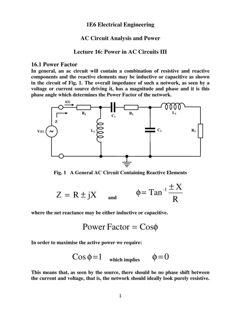
1E6 Electrical Engineering AC Circuit Analysis and Power Lecture 16: Power in AC Circuits III 16.1 Power Factor In general, an ac circuit will contain a combination of resistive and reactive components and the reactive elements may be inductive or capacitive as shown in the circuit of Fig. 1. The overall impedance of such a network, as seen by a voltage or current source driving it, has a magnitude and phase and it is this phase angle which determines the Power Factor of the network. i(t) R1 L2 R2 C1 Z V(t) ~ C2 L1 R3 Fig. 1 A General AC Circuit Containing Reactive Elements Ζ = R ± jX φ = Tan -1 and ±X R where the net reactance may be either inductive or capacitive. Power Factor = Cosφ In order to maximise the active power we require: Cos φ = 1 which implies φ=0 This means that, as seen by the source, there should be no phase shift between the current and voltage, that is, the network should ideally look purely resistive. 1 The overall impedance of an ac network can be expressed in terms of constituent components which include an equivalent resistance, an equivalent inductance giving a positive reactive component and an equivalent capacitance giving a negative reactive component. Then: Impedance = Resistance + Inductive Component + Capacitive Component Ζ = R EQ + jX LEQ − jX CEQ If XLEQ = XCEQ, then the net reactive component of the impedance is zero so that: Ζ = R EQ φ = Tan -1 ±X =0 R Power Factor = Cosφ = 1 If this is the case then and Sinφ = Sin 0 = 0 Apparent Power = Active Power = VRMSI RMS = Reactive Power = j VRMS I RMSSin φ = j Vm I m 2 Vm I m Sin φ = 0 2 This means that, in this case, all of the power delivered to the network by the source is dissipated in the resistive elements. That is, all of the power delivered is consumed and becomes useful or “active” power. Therefore, in order to correct the power factor of any ac network to unity, the net effective reactance must be made equal to zero. This is achieved by making the capacitive reactive component of the impedance equal and opposite to the inductive reactive component. If the network has only one type of reactance then a reactance of the opposite type must be added in order to neutralise it. 2 16.2 Case Study: Consider the electrical equivalent of a motor driving a load illustrated by the equivalent electric circuit shown in Fig. 2. Note that the resistance primarily represents physical work done by the motor in driving a mechanical load. It also includes the resistance of the coil windings which generate heat when a current flows through them and consequently also dissipate power. f = 50Hz Z ~ L motor inductance 200 mH ωL = 314 x 200 x 10 −3 = 62.8Ω V= 310 Sin ωt R load 50 Ω R = 50Ω Fig. 2 An Equivalent Electric Circuit having Reactance Ζ = R + jω L Z = R 2 + ω 2 L2 Z = 2500 + 3943 .8 = 80.3Ω φ = Tan -1 Im = ωL 62.8 = Tan -1 = 51.5o R 50 Vm 310 = = 3.86 A and Cosφ = Cos51.5 o = 0.623 Z 80.3 3 Then the power consumption is characterised as: Apparent Power = PAPP = Active Power = PAVE = Vm I m 310 x 3.86 = = 598W 2 2 Vm Im 310 x 3.86 Cosφ = x0.623 = 373W 2 2 Reactive Power = PIMAG = j Vm I m 310 x 3.86 x0.783 = j468W Sinφ = j 2 2 This shows that the motor draws approximately 600W of power from the mains supply overall. However, less than 400W of this is consumed as energy and used by the motor to do mechanical work. A further power of more than 450W is drawn from the supply, which can be considered as out of phase with the active power, and is returned to the supply at a later point in each cycle. The important point to note is that the supply must be able to generate and provide the total apparent power. That is, the source must be rated to handle a total power of 600W when less than 400W is used by the load. This means that the source must have a power handling capacity which is more than 50% greater than that required to deliver the useful power. 4 16.3 Power Factor Correction Consider including a capacitor to neutralise the effect of the motor inductance and correct the Power Factor as shown in Fig. 3. Z ~ L motor inductance 200 mH V= 310 Sin ωt R load 50 Ω Fig. 3 Correction of the Power Factor of the Circuit of Fig. 2 1 jω C Ζ= 1 R + jωL + jωC (R + jωL ) Ζ = R EQ + jX LEQ − jX CEQ Multiplying the numerator and demoninator above by jωC: Ζ= Ζ= Rationalising: C Power Factor correction capacitance (R + jωL ) jωCR − ω2 LC + 1 (R + jωL ) (1 − ω LC)+ jωCR 2 ( R + jωL ) [(1 − ω2 LC)− jωCR ] Ζ= (1 − ω2LC)2 + (ωCR )2 5 Ζ= ( ) ( ) R 1 − ω2 LC + jωL 1 − ω2 LC − jωCR 2 + ω2 LCR (1− ω LC) + (ωCR ) 2 2 Ζ= 2 R − ω2 LCR + jωL − jω3L2C − jωCR 2 + ω2 LCR (1− ω LC) + (ωCR ) 2 2 Ζ= 2 R + jωL − jω3L2C − jωCR 2 (1− ω LC) + (ωCR ) R + jωL − jωC(ω L + R ) Ζ= (1− ω LC) + (ωCR ) 2 2 2 2 2 2 2 2 2 Breaking this into its equivalent components gives: R EQ = R (1− ω LC) + (ωCR ) jX LEQ = 2 2 2 jωL (1− ω LC) + (ωCR ) - jX CEQ = 2 2 − jωC ω2 L2 + R 2 ) 2 ( (1− ω LC) + (ωCR ) 2 2 2 From this the equivalent resistive, inductive and capacitive components can be identified. It is clear that cancellation of the inductive and capacitive components requires that the values of the positive and negative imaginary terms must be equal but opposite. This requires: ωL = 2 ( ωC ω2 L2 + R 2 ) (1− ω LC) + (ωCR ) (1− ω LC) + (ωCR ) 2 2 6 2 2 2 Which gives: ( ωL = ωC ω2 L2 + R 2 ( L = C ω2 L2 + R 2 C= So that ) ) L ω2 L2 + R 2 For the component values given of L = 200mH, R = 50Ω at a frequency of 50Hz 200 x 10−3 200 x 10−3 0.2 0.2 x 10⁶ C= = = = µF 2 2 62.8 + 50 3943.8 + 2500 6443.8 6443.8 C = 31µF Then with the net reactance eliminated: Ζ = R EQ = R (1− ω LC) + (ωCR ) 2 2 2 For the values given of R = 50Ω, L = 200mH and C = 31µF: R EQ = R EQ = In this case 50 (1 − 314 2 ) ( 2 x 0.2 x 31 x 10− 6 + 314 x 31 x 10− 6 x 50 ) 2 50 50 50 = = = 128.2Ω 2 2 0.15 + 0 .24 0 . 39 (1 − 0.61) + (0.49) Im = Vm Vm 310 = = = 2.42 A Ζ R EQ 128.2 7 Then for the modified circuit with the Power Factor CosФ = 1 PAPP = PAVE = Vm I m 2 = 310 x 2.42 = 375 W 2 and with SinФ = 0 Reactive Power = PIMAG = j Vm I m 310 x 3.86 Sinφ = j x 0 = 0W 2 2 Note that the average or active power has not been increased but in fact remains the same. The apparent power, however has been reduced so that the power which must be delivered by the source is also reduced. In fact, the inactive, reactive or imaginary power has been eliminated from the point of view of the source which no longer has to generate this power. This means that all of the power drawn from the source is now only useful active power and no surplus power is demanded which is not used. In practice some reactive power is drawn from the source during initial transient conditions then this power oscillates between the inductance and the capacitance present under steady state conditions but is not dissipated. 8
