Calculation Lab Problems (for CE 1202 Students Only)
advertisement

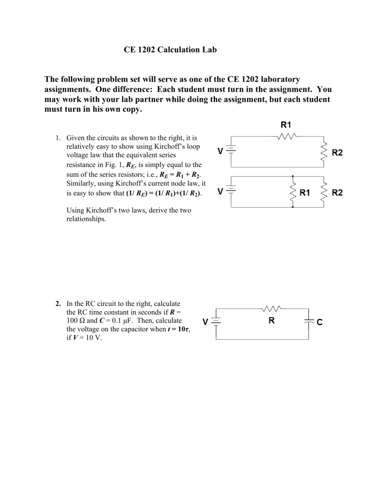
CE 1202 Calculation Lab The following problem set will serve as one of the CE 1202 laboratory assignments. One difference: Each student must turn in the assignment. You may work with your lab partner while doing the assignment, but each student must turn in his own copy. 1. Given the circuits as shown to the right, it is relatively easy to show using Kirchoff’s loop voltage law that the equivalent series resistance in Fig. 1, RE, is simply equal to the sum of the series resistors; i.e., RE = R1 + R2. Similarly, using Kirchoff’s current node law, it is easy to show that (1/ RE) = (1/ R1)+(1/ R2). Using Kirchoff’s two laws, derive the two relationships. 2. In the RC circuit to the right, calculate the RC time constant in seconds if R = 100 Ω and C = 0.1 μF. Then, calculate the voltage on the capacitor when t = 10τ, if V = 10 V. 3. Find the frequency of oscillation and the damping factor α in seconds for the following DC circuit, if V = 10V, R = 50 Ω, L = 10 mH, and C = 10 μF. In how much time will the transient effects have died out? Assume the circuit is stable after αt = 10. 4. Given the AC circuit to the right, find the AC current, i(t), as a function of time if V = 10 cos(1000t), R = 500Ω, and C = 1 μF. 5. Find i(t) if V = 10 cos(1000t), R = 500Ω, and L = 100 mH. 6. Because inductive and capacitive impedance have the opposite sign in the ω-domain, these quantities can “cancel out” reactive current if they are in the same circuit. This turns out to be very important in the real world, as all industries represent an inductive load to the power company, so adding banks of capacitors where power enters the company grid can reduce the inductive current. Inductive current is “imaginary” mathematically, but it is real physically, and the power company charges us for it! Reducing reactive current will reduce the power bill. In the circuit above, how much capacitance would have to be added to cancel out the inductive impedance if the inductance is one Henry, and the AC frequency is 60 Hz? Remember, ω = 2πf. 7. In the ω domain, series impedances add up directly and parallel impedances add up reciprocally, just as resistances behave in the time domain. Thus in the upper circuit, the impedance Z is: Z Series R (1 / jC ) j L . R 1/jωC 1/jωC R jωL jωL Similarly, the parallel impedance relationship is represented by: 1 Z Parallel 1 1 1 1 1 jC R (1 / jC ) j L R j L We can use these equations to develop relationships for series and parallel inductances and capacitances. jωL1 V Consider the series inductor circuit at right in the ω domain. There must be some equivalent inductance LE (second circuit) that is the equivalent inductance of the two series inductors L1 and L2. How do we find this equivalent inductance? jωL2 V jωLE In the first circuit, we have the ω domain relation that ZTotal j L1 j L2 . Similarly, in the second circuit, ZTotal j LE . Since if two things are equal to the same thing, they are equal to each other, then: j L1 j L2 j LE . Dividing by jω, then L1 L2 LE , or LE L1 L2 Thus, series inductances add directly. Now, using the definitions of impedances in the ω domain, determine the relationships of parallel inductances, series capacitances, and parallel capacitances. See the next page for helpful diagrams. V jωL1 jωL2 V jωLE Equivalent inductance of parallel inductances. 1/jωC1 1/jωC2 V 1/jωCE V Equivalent capacitance of series capacitances. V 1/jωC1 1/jωC2 Equivalent capacitance of parallel capacitances. V 1/jωCE


