Renewable sources of electricity

Micro generation | 11
Renewable sources of electricity – a brief overview
THE SCOPE of the 17th Edition is wider and contains many new requirements, including additional requirements to ensure the safe connection of low-voltage generating sets including small-scale embedded generators and solar photovoltaic (PV) power supply systems. In this article we look at the new
Regulations in Section 551 and Section 712.
Chapter 55 – Other Equipment.
Regulation 551 – Low Voltage
Generation Sets
This set of Regulations now includes additional requirements contained in Regulation 551.2 to ensure the safe connection of low-voltage generating sets including small-scale embedded generators.
A new Regulation, 551.4.2, E
How to ensure the safe connection of low-voltage generating sets including small scale embedded generators and solar photovoltaic (PV). This article is repeated from a previous edition of Wiring
Matters, and clarifies important issues.
By Geoff Cronshaw
By Geoff Cronshaw
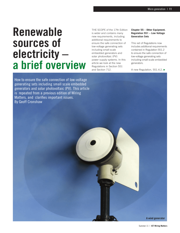
A wind generator
Summer 11 | IET Wiring Matters
12 | Micro generation
F regarding the use of RCDs, has been added. Regulation
551.4.2 states:
“The generating set shall be connected so that any provision within the installation for protection by RCDs in accordance with Chapter 41 remains effective for every intended combination of sources of supply.”
Notes have been added including one to Regulation
551.1 stating that the procedure for connecting generating sets up to 16 A in parallel with the public supply is given in ‘The Electricity
Safety, Quality and Continuity
(Amendment) Regulations
2006’. For sets above 16 A the requirements of the distributor must be ascertained. The 17th
Edition recognises that there are two connection options:
(i) Connection into a separate dedicated circuit
(ii) Connection into an existing final circuit
Connection into a dedicated circuit is preferred. Regulation
551.7.2 sets out the requirements for the two options. The Regulation requires that a generating set used as an additional source of supply in parallel with another source shall either be installed on the supply side of all protective devices for the final circuits of the installation
(connection into a separate dedicated circuit) or if connected on the load side of all protective devices for the final circuits must fulfil a number of additional requirements.
These additional requirements are:
(i) the current carrying capacity of the final circuit conductors shall be greater than or equal to the rated
IET Wiring Matters | Summer 11
Micro generation | 13
current of the protective device plus the rated output of the generating set, and
(ii) A generating set shall not be connected to a final circuit by a plug and socket, and
(iii) A residual current device providing additional protection of the final circuit in accordance with Regulation
415.1 shall disconnect all live conductors including the neutral conductor, and
(iv) The line and neutral conductors of the final circuit and of the generating set shall not be connected to earth, and
(v) Unless the device providing automatic disconnection of the final circuit in accordance with
Regulation 411.3.2 disconnects the line and neutral conductors, it shall be verified that the combination of the disconnection time of the protective device for the final circuit and the time taken for the output voltage of the generating set to reduce to
50 V or less is not greater than the disconnection time required by Regulation
411.3.2 for a final circuit.
PV Installation
Section 712 of BS 7671:2008 is concerned with the safe installation of solar photovoltaic (PV) power supply systems. A PV system is a collection of interconnected PV cells that turn sunlight directly into electrical energy.
The risks
Modules produce electricity when exposed to daylight. This needs to be taken into account during design, installation, use and maintenance. Also, the electrical installation which incorporates a PV system has a second source of energy which needs to be isolated before starting work. A further risk involves working at height E
PV installations require expertise in dc wiring and fault protection for d.c. side of the installation
Summer 11 | IET Wiring Matters
14 | Micro generation
F on a roof, for example together with the manual handling associated with a PV installation. Finally, PV installations require expertise in dc wiring and fault protection for d.c. side of the installation.
Scope
Section 712 of BS 7671:2008 applies to the electrical installations of PV power supply systems including systems with a.c. modules.
Section 712 does not apply to
PV power supply systems which are intended for standalone operation.
The Electricity Safety, Quality and Continuity (Amendment)
Regulations 2006
Solar photovoltaic (PV) power supply systems are required to meet the Electricity Safety,
Quality and Continuity
(Amendment) Regulations
2006 (ESQCR) as they are embedded generators. These are mandatory requirements.
However, where the output does not exceed 16 A per line they are small-scale embedded generators (SSEG) and are exempted from certain of the requirements provided that:
(i) the equipment should be type tested and approved by a recognised body,
(ii) the consumer’s installation should comply with the requirements of BS 7671,
(iii) the equipment must disconnect itself from the distributor’s network in the event of a network fault, and
(iv) the distributor must be advised of the installation before or at the time of commissioning.
See ‘Engineering
Recommendations G83/1, for
PV systems up to 16A (5kw) and G59/1’, published by the
Energy Networks Association
(ENA) for larger systems and generators, etc. Further information can be obtained at: www.ena-eng.org.
Protection for safety
General requirements
Regulation 712.410.3 requires that PV equipment on the dc side must be considered to be energised, even when the system is disconnected from the a.c. side. This is because modules produce electricity when exposed to daylight.
Regulation 712.410.3.6 states that the protective measures of non-conducting location and earth-free local equipotential bonding are not permitted on the d.c. side.
Regulation 712.412 gives requirements for the protective measure, double or reinforced insulation and states that protection by Class II or equivalent insulation shall preferably be adopted on the d.c. side. Regulation 712.414 gives requirements for the protective measure, extra-low voltage provided by SELV or
PELV. Where this method of protection is used Uoc STC replaces Uo and must not exceed 120 v dc.
Protection against overcurrent and electromagnetic interference
Regulation 712.433 gives a relaxation, and allows overload protection on the d.c. side to be omitted when the current carrying capacity of the cable is equal to or greater than 1.25 times Isc STC (short-circuit current under standard test conditions) at any location.
Regulation 712.434 requires that the PV supply cable on the a.c. side shall be protected against fault current by an overcurrent protective device installed at the connection to the a.c. mains.
Protective measures
Regulation 712.41 recognises three methods of protection.
Regulation 712.411 gives requirements for the protective measure, automatic disconnection of supply.
Where this method of protection is used on the a.c. side, the PV supply cable shall be connected to the supply side of the protective device for automatic disconnection of circuits supplying current using equipment.
Regulation 712.444 deals with
Protection against electromagnetic interference
(EMI) in buildings. The
Regulation recognises that in order to minimise voltages induced by lightning, the area of all wiring loops shall be as small as possible.
Selection and erection of equipment
Compliance with standards
Regulation 712.511 requires that PV modules shall comply with the requirements of the relevant equipment standard, e.g. BS EN 61215 for crystalline PV modules.
Operational conditions and external influences
Electrical equipment on the d.c. side must be suitable for direct voltage and direct current as required by
Regulation 712.512.
Equipment approved to normal a.c. standards may not be suitable, especially switchgear.
It is therefore essential that PV systems are installed by competent persons to an approved design. The designer must clarify the standards and performance requirements with the equipment manufacturers as part of the design process. It must also be remembered that as PV systems are often installed on a roof or other location external to the building they will be subject to external influences such as heavy rain, high winds, etc. and therefore need to be designed and installed to withstand such conditions.
Also, it must also be remembered that planning and building regulations approval may be required.
Accessibility
Regulation 712.513 requires that the selection and erection of equipment shall facilitate safe repair and maintenance.
Wiring systems
Regulation 712.522 requires that PV string cables, PV array cables and PV d.c. main cables shall be selected and erected so as to minimise the risk of earth faults and short-circuits. Cables should be selected that are suitable for their environment and conditions of use and the expected equipment temperatures. The Regulations require that wiring systems must be able to withstand the expected external influences such as wind, ice formation, temperature and solar radiation.
Isolation, switching and control
Regulation 712.537.2.1.1 recognises the need for maintenance and requires that a means of isolating the a.c. and d.c. sides of the PV convertor needs to be provided.
IET Wiring Matters | Summer 11
XXXXXXXXXXXXXXXXXX | 15
WARNING - DUAL SUPPLY
ISOLATE BOTH MAINS AND ON-SITE GENERATION
BEFORE CARRYING OUT WORK
ISOLATE THE MAINS AT ____________________________________
ISOLATE THE GENERATOR AT _______________________________
Regulation 712.537.2.2 has contact as possible with d.c. requirements for the selection cables and a.c. cables and and erection of isolation and switching devices. The accessories.
Regulation states that the selection and erection of
Labelling
Labels are required at the: devices for isolation and switching to be installed between the PV installation and the public supply, the public supply shall be considered the source and the
PV installation shall be considered the load.
Earthing arrangements and protective conductors
Conclusion
There are a wide range of microgeneration technologies including: Solar photovoltaic
(PV), wind turbines, Small supply terminals (fused cut-out) meter position consumer unit, and at all scale hydro and Micro CHP
(Combined heat and power).
Microgeneration systems such as solar PV installations should always be carried out by a trained and experienced the points of isolation to installer. For example, the roof indicate the presence of the must be strong enough to take
SSEG within the premises their weight, especially if the
The Health and Safety (Safety panel is placed on top of
Signs and Signals) Regulations existing tiles. It is also
1996 stipulate that the labels important to note that there are
Regulation 712.54 requires that where protective bonding conductors are installed, they shall be parallel to and in as close should display the prescribed mandatory requirements triangular shape and size using concerning the parallel black on yellow colouring. A typical label both for size and content is shown above. connection of generators with the supply network.
For further information refer to
‘BS 7671:2008, Engineering
Recommendations G83/1 and
G59/1’ published by the
Energy Networks Association and the Department for
Business, Enterprise &
Regulatory Reform (BERR).
Further information
England and Wales – the
Department of Communities and Local Government www.communities.gov.uk
Scotland – The Scottish
Building Standards Agency www.sbsa.gov.uk
This article is repeated from a previous edition of Wiring
Matters, and clarifies important issues.
Summer 11 IET Wiring Matters


